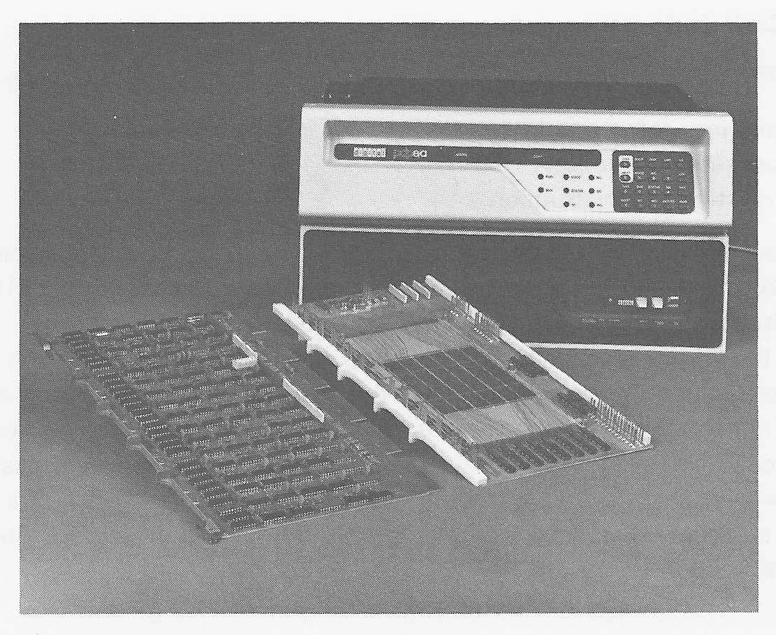
 FIGURE 10.1 A PDP-8A computer, the
most recent version of the very successful PDP-8 architecture. The two
boards in the foreground are the central processor (left) and the memory
(right). (Photo courtesy of Digital Equipment Corporation.)

As was admitted in the last chapter, there is no real MIX computer. MIX computers are simulated on other machines. However, the MIX computer is very similar to many existing computers. To illustrate this, we present here a description of some of the more common computers in use today. We do not attempt to teach you how to program in the assembly language of each of these computers; we present them for two reasons. First, after your extensive work with MIX, and the brief description of the computer given here, it should be obvious that, given about a week to familiarize yourself with a reference manual describing the hardware instruction set and the assembly language, you could be programming on any of these computers as well as you currently program for the MIX computer. Second, it is unlikely that you will only work on one computer in your life. Thus, this chapter will give you a familiarity with the different types of computers which currently exist. This will allow you to move easily from machine to machine, including new designs or machines which you have not seen before.
We begin with a brief history and survey of recent computers.
The first commercial computer sold in the United States was the Univac I in 1951. The Univac I was produced by the Univac division of the Remington Rand Corporation (later to become Sperry Rand). The Univac I was a very sophisticated machine, for its time, and established Univac as the leader in the computer market. The Univac I was followed up by the Univac II in 1957 and the Univac III in 1960. These were all commercial machines aimed towards business data processing.
Univac was also building computers for the scientific research market. In 1952, the Univac 1103 was built, followed later by the 1107. These were early vacuum tube computers, and were eventually replaced by the larger, faster 1108 and 1106 in 1964. In 1970, the 1110 was announced. The Univac 1108 and 1110 are very powerful scientific computers which normally execute under the EXEC-8 operating system.
Univac was not the only computer manufacturer in the early 1950s, however. The International Business Machines Corporation (IBM) had for a long time sold punched card equipment as well as general office equipment. Their early 701 (1952) computer was later replaced by the 704 (1954) and the 709 (1957). These vacuum tube computers were superseded by the 7070 and the 7090 (1958) and 7094 (1962). The 7090 and 7094 computers were very popular and considered the best scientific computers of their day. The 1401 (1959) and 1410 (1960) were very successful for commercial data processing problems.
IBM, by 1960, could see the tremendous market which was developing for computers and computer services. They could also see that there was a wide range of uses for computers, so that one computer would not be able to meet the diverse demands of small businesses and large scientific computing. But each different computer required its own hardware, maintenance, and software. To try to limit the cost of producing different software and hardware for different computers, IBM in 1964 announced its System 360 family of computers. Originally six models (30, 40, 50, 60, 62, 70) were announced to handle the range of computing problems from small systems (the model 30), through medium sized systems (models 40 and 50), and on to larger systems (the models 60, 62, and 70). The entire family utilized the same hardware, architecture, and instruction set and I/O devices (with some exceptions). Any program which was programmed for one model could also be used on another model. Thus, IBM could provide excellent support for a large range of computing problems with one family of internally compatible computers.
This approach was immensely successful, with the 360 establishing itself as the major computer on the market. Some models were dropped and others added as technology and demand changed, but the basic architecture remained the same. A user could, if his workload increased, move up from his current model to the next larger model and still retain his existing software and I/O devices. Compilers, assemblers, loaders, and the operating systems (DOS/360 and OS/360) all run on all of the models (more or less). The larger models were simply faster and could support more services than the smaller models. Eventually fourteen models were produced (20, 22, 25, 30, 40, 44, 50, 65, 67, 75, 85, 91, 95,195).
In 1970, IBM announced their 370 series (models 115, 125, 135, 138, 145, 148, 155, 158, 165, 168), which represented an evolutionary compatible improvement over the 360 family. Some problems of the 360 design were corrected, and some new features added. The technology of construction was changed so that the 370s are faster, but from an architectural point of view the 370s are simply a continuation of the 360 line.
Although the basic idea of using one family of computers to span the range of demand for computers is reasonable, economic realities make it nearly impossible to achieve in practice. The major problem is at the low end, where very simple, inexpensive systems are needed by small businesses. The IBM System/3 (1969) is aimed at this market and has been relatively successful. Recently the System/32 has been introduced as an even smaller system, aimed at situations where there is no resident programming staff (like the typical office). Similar demands for small to medium scientific computers resulted in the IBM 1620 and its successor the IBM 1130. The IBM 1800 and the follow-on System/1 were also aimed at process control and scientific laboratory requirements. The Series/1 (1977) is aimed at this market too.
At the other end of the computer market are the users of large scientific computers. The 370/168 is IBM's main machine in this area. One of the principal designers of the 360, Gene Amdahl, left IBM after the announcement of the 370 series. He formed his own company which is now producing its own computer, the Amdahl 470V/6. The Amdahl computer uses the same instruction set as the IBM 360/370 series (thus allowing software developed for the IBM computers to be run on the Amdahl computer), but is about twice as fast as the IBM 370/168 at a slightly lower price (from $4 million to $6 million, depending on the amount of memory wanted).
The forming of a competing company by ex-employees of a company is not unheard of in the computer field. As early as 1957, a group of Univac employees left Univac and formed their own company, Control Data Corporation (CDC). Their first computer was the CDC 1604 (1960), followed by the 3600 in 1963. These were medium-sized machines. In 1964, however, CDC announced their CDC 6600 computer, the largest and fastest computer system then available. The 6600 (and other 6000 series machines, the 6400, 6500, and 6700) was aimed at the large scientific computer market and particularly the need for massive computing power of the Atomic Energy Commission. In 1968, the 7600, successor to the 6600 was announced. The 7600 was 7 to 8 times faster (20 million instructions per second) than the 6600 and generally cleaned up some of the design problems of the 6600. The 6000 and 7000 series were renamed the Cyber 70 series in 1970, but this was mainly a marketing move.
In 1972, the chief designer of the CDC 6600, Seymour Cray, left CDC to form his own company (backed in part by CDC and Fairchild, a leading semiconductor component manufacturer). Cray Research, Inc., has now produced the CRAY-1 computer, a very large powerful scientific computer. Unlike the Amdahl computer, however, which is identical to IBM's 370 in architecture, the CRAY machine has an architecture and instruction set which, although vaguely similar, differs from the CDC computers. Thus, entirely new software will need to be developed.
Many other companies also manufacture computers. The Burroughs Corporation has built computers for many years. Their most popular large machine was the B5500, a successor to the B5000. The B5500 was succeeded by the larger, newer B6500, B7500, and B8500 computers. All of these machines were designed with both hardware and software in mind and represent architecturally different concepts from the standard register machines. The Burroughs machines are stack machines. A stack machine is particularly appropriate for executing code written in a high level language like Algol, so that no assembly language programming need be done on the Burroughs machines; there are no assemblers. All programming is done in a higher-level language, or an intermediate language called a systems programming language. Even the operating system, MCP (Master Control Program), is written in the systems programming language.
Univac, IBM, and Burroughs are all companies which have entered the computer field from the business side of computing, having been involved in office machines, forms, and service before producing computing equipment. The other side is, of course, the electronics field. General Electric, RCA, and Honeywell were all well-established electronics firms before entering the computer field.
General Electric produced three lines of computers: the 200 series, 400 series, and 600 series. Some significant software was developed for these systems. The Basic programming language was originally developed at Dartmouth College for a GE 235 computer, and has since spread to almost all computer systems. The 600 series, the larger computers in GE's product line, gave rise to the GECOS operating systems and the MULTICS operating system of MIT's Project MAC. However, GE's computer division consistently lost money, and so in 1970 GE withdrew from the commercial computer manufacturing market. Its computer division was sold to Honeywell, which has merged it into its own computer operations.
RCA was an early pioneer in computer technology, but never seemed to be able to take advantage of this position. Its major computer line, the Spectra 70 series, was compatible with the IBM System 360 family, having the same architecture and instruction set. Although there were some price/performance advantages to some of the RCA models, sales did not go well, and in 1972 RCA sold its computer division to Univac.
A more complicated history starts with the Scientific Data Systems (SDS) computer firm. This California-based company produced two lines of computers. The 900 series started in 1962 with the 910 and 920, and continued with the 930, 940, and 945 models. These computers were used for some of the early time-sharing systems. In 1965, to compete with IBM's System 360, SDS produced the Sigma line of computers. The Sigma 2 and Sigma 7 were superseded by the Sigma 3 and Sigma 5. The users of these computers thought highly of their design as medium-sized scientific computers.
In 1969, Xerox Corporation bought SDS, changing its name to Xerox Data Systems (XDS), in an attempt to enter the computer field. New computer models were introduced in 1973, the Xerox 530 to replace the Sigma 3 and the 550 and 560 to replace the Sigma 5. However, these did not sell well, and in 1975 Xerox withdrew from the computer field, selling its computer division to Honeywell.
The major problem in the medium and large computer market is, of course, competing with IBM. The most successful strategies have been to concentrate on a particular segment of the computer field, and not try to cover the entire market. This has been particularly successful in the minicomputer market where computers are used as laboratory and control devices.
The Digital Equipment Corporation (DEC), is the IBM of the minicomputer market. One of its most successful computers is the PDP-8 (1965). This small machine is extremely limited, but also very inexpensive. (Originally under $10,000 and now around $2,000). It has become, and remains, very popular. The PDP-11 (1969) has also become a very popular computer. These smaller computers complement the DEC-10, a large time-sharing computer whose roots lie in the PDP-10 and PDP-6 computers.
DEC is not the only minicomputer manufacturer, however; far from it. Data General (DG) started in 1968, by a group of ex-DEC employees, produces the NOVA line of minicomputers. Hewlett-Packard's 2116 developed in 1967 to compete with the PDP-8, was followed by the HP 2100 and HP 21MX computers. The Interdata Corporation's 7/32 computer is architecturally similar to an IBM 360. Minicomputers are also produced by General Automation, Varian, Prime, Modular Computer Systems, Computer Automation, Harris, Datum, Cincinnati Milacron, Lockheed Electronics, Tandem Computers, MITS, Texas Instruments, Raytheon Data Systems, and many more.
Even smaller computers, the microcomputers, are now being produced. The heart of these systems is a microprocessor which puts all the functions of a central processing unit on just one or a few semiconductor chips. The Intel 8080 and Motorola 6800 microprocessors seem to be the two most popular micro-processors. The Intersil IM6100 executes the PDP-8 instruction set, and the PDP-11 instruction set is available in an LSI-11 microprocessor. Microprocessors are being used in many applications where simple control functions can be easily programmed, and also by a growing number of people who build and program their own computers as a hobby.
This discussion gives you some familiarity with the names of common computers. Now, we briefly present the architecture of a selected set of common computers to give you a better understanding of their structure.
The PDP-8 is a small but easy to use and simple computer. It was first sold in 1965. Since then several versions have been manufactured as new hardware technology became available. The PDP-8/I, PDP-8/E, PDP-8/S, PDP-8/L and PDP-8/A are all models of this same computer. The PDP-8 is a product of the Digital Equipment Corporation. It is mainly used in dedicated data collecting or control functions, like running steel mills, medical laboratory experiments, or monitoring air pollution. The PDP-8/A was available with a CRT terminal for about $5,000.
 FIGURE 10.1 A PDP-8A computer, the
most recent version of the very successful PDP-8 architecture. The two
boards in the foreground are the central processor (left) and the memory
(right). (Photo courtesy of Digital Equipment Corporation.)
The PDP-8 is a 12-bit binary machine. It uses two's complement arithmetic. With 12-bit addresses, up to 4096 words of memory can be addressed, so most PDP-8's have 4K of main memory. There are two registers in the PDP-8, the A register (a 12-bit accumulator) and the Link bit. There is also a 12-bit program counter, but this is not directly accessible to the programmer. A block diagram of the PDP-8 is shown in Figure 10.2.
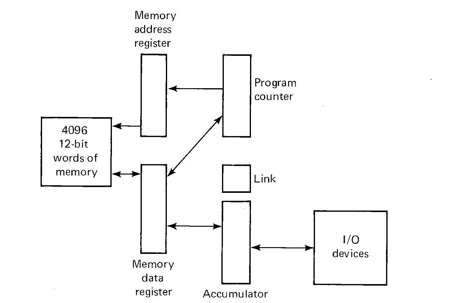 FIGURE 10.2 A block diagram of the PDP-8. All registers
except the Link bit are 12 bits.
The PDP-8 has eight instructions. These can be grouped into three classes:
One technique is indirect addressing. One bit associated with each memory reference instruction specifies whether the address in the instruction is (0) the address of the memory location wanted (no indirection), or (1) the address of the address of the memory location (indirect addressing). Indirect addressing is at most one level. In order to specify the entire 4K memory, all 12 bits of a memory location are needed, so there is no bit left over in a 12-bit word to indicate if further indirection is needed.
This leaves us with eight bits in the instruction with which to specify an address. One more bit is used to specify a page. Memory is considered to be split into 32 pages of 128 words. The first page is addresses 0000 to 0177 (octal), the next page is from 0200 to 0377 (octal), 0400 to 0577 (octal), and so forth. In effect, a 12-bit address is broken into two parts: a 5-bit page number and a 7-bit location within a page.
Each memory reference instruction has one bit which is used to specify what page the address is on. This bit specifies that the address is either (0) on the zero page (locations 0000 to 0177) or (1) on the current page (same page as the current instruction). The remaining seven bits in the instruction specify the location in the page. This scheme allows certain locations (zero page) to be accessed by any instruction (allowing global variables), while the current page can be used to store local variables.
 FIGURE 10.3 Memory reference instruction format (PDP-8)
The memory reference instruction format is given in Figure 10.3. To interpret the instruction at location P, the Z/C bit is examined. If Z/C is zero, the high-order five bits of the memory address are zero (zero page); if Z/C is one, the high order five bits of the memory address are the same as the high order 5 bits of the address P (current page). The low-order seven bits are the address field of the instruction. This specifies a 12-bit memory address. Now if the D/I bit is zero, then this is the effective address (direct addressing); if the D/I bit is one, then the contents of the memory address are fetched, and these contents are the effective address (indirect addressing). The effective address is used in all memory reference instructions.
There are six memory reference instructions:
| Instruction | Mnemonic | Opcode | Time |
| Logical AND | AND | 0 | 2 |
| Two's complement add | TAD | 1 | 2 |
| Increment and skip if zero | ISZ | 2 | 2 |
| Deposit and clear accumulator | DCA | 3 | 2 |
| Jump to subroutine | JMS | 4 | 2 |
| Jump | JMP | 5 | 1 |
The time for each instruction is the number of memory cycles needed. The actual time varies from 1.5 to 8 microseconds per memory cycle, depending upon the model. Indirect addressing adds another memory cycle, of course.
In more detail, the instructions are
These instructions are a little different, but very similar to some instructions in the MIX machine. TAD is addition to the A register. DCA is a store into memory. AND is used for masking. JMP allows transfer of control. JMS stores the return address in the first word of the subroutine and starts execution at the next location; a JMP indirect through the entry point will return to the main program. The ISZ instruction is used for loops. The negative of the number of loop iterations wanted is stored in memory some place, then the ISZ instruction counts each loop. If the count is nonzero, the next instruction (a JMP to start of loop) is executed; when count is zero, we skip over the JMP and continue.
For example, to multiply the A register by 10, (where X has -10, and Y is a temporary)
There are still a large number of things we want to do as programmers. The Operate instruction is a special instruction which allows for many different functions. These functions are encoded in a very few bits. The operate instruction specifies operations which affect only the A register, Link bit, and program counter. Thus, the space used in memory reference instructions for specifying a memory address can be used for other purposes. There are two formats for the operate instruction; these are called group 1 and group 2 operate instructions. Bit 8 distinguishes between these two groups. The instruction format is shown in Figure 10.4.
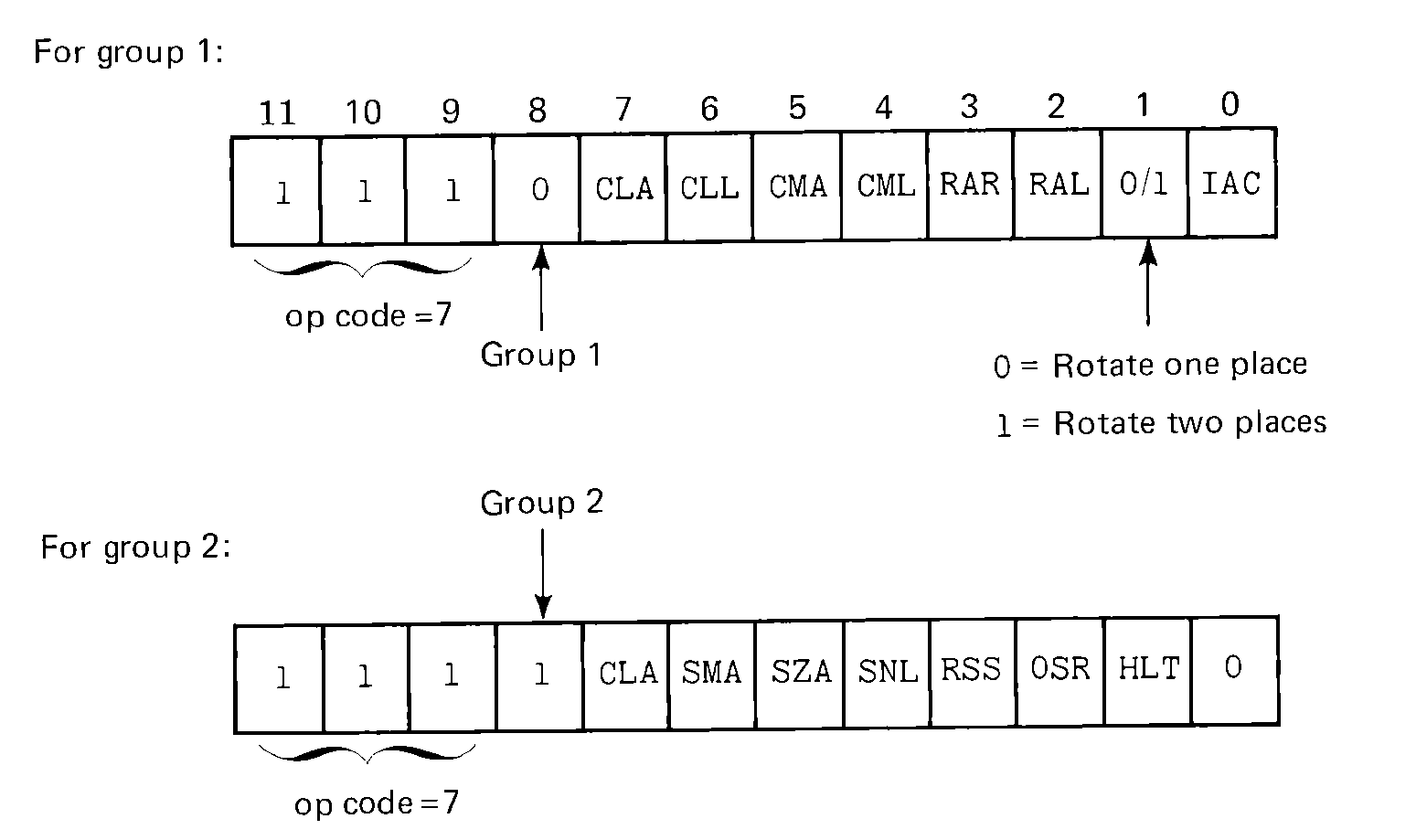 FIGURE 10.4 Format of the operate instruction of the PDP-8.
The effect of the operate instruction is determined by which of the subinstructions are selected. Each subinstruction is selected by setting the corresponding bit to one. The subinstructions are:
These subinstructions can be combined independently of each other to form more complicated instructions. Thus,
| CLA | Clear the A register. |
| CLA CLL | Clear both the A register and the Link. |
| CLA CMA | Clear the A register, then complement (set the A register to all ones). |
| CMA IAC | Complement and add 1 (two's complement). |
| CLL RAL | Clear Link; rotate one place left (multiply the A register by two; put sign bit in Link). |
| SMA SZA | Skip if the A register is less than or equal to zero. |
| CLA SZA | First, test if A is zero or not. Then clear A. If A was zero, skip next instruction. |
This last example points out that the order in which the subinstructions are executed is very important. The PDP-8 interprets these instructions for group 1 as follows:
Possible combinations are a subset of
CLA, CLL, CMA, CML, IAC, (RAR, RAL, RTR, or RTL)or
SMA, SZA, SNL, RSS, CLA, OSR, HLTAny subset of the instructions may be selected, but only one of the RAR, RAL, RTR, or RTL subinstructions may be selected per operate instruction.
Bit 0 of a group 2 operate instruction is always zero. Setting this bit to one (leaving bits 11, 10, 9, and 8 one) specifies an additional set of instructions which are executed by an Extended Arithmetic Element (EAE) for doing multiplies, divides, and shifts. The EAE is an optional feature of the PDP-8 (and costs extra).
Several assembly languages for the PDP-8 exist. One is the PAL-III assembler. It is extremely simple, since the assembler must run on such a small computer. Most assembly language statements are of the form:
| NOP | No instructions selected; no operation | |
| SPA | SMA RSS (Skip on Positive A register) | |
| SNA | SZA RSS (Skip on Nonzero A register) | |
| SZL | SNL RSS (Skip on Zero Link) | |
| SKP | RSS (Always skip) | |
| CIA | CMA IAC (Complement and Increment A register) | |
| LAS | CLA OSR (Load A register from Switch Register) | |
| STL | CLL CML (Set Link) |
Comments are indicated by the slash and continue to the end of the card. Indirect addressing is indicated by the letter I. The symbol "." (period) refers to the value of the location counter. Fields can be either symbols or octal numbers or the period.
Only two pseudo-instructions are recognized. The ORIG function in MIX is accomplished in the PDP-8 by an assembly language statement of the form,
The PAL-III assembler is a two-pass assembler (or three-pass if you want a listing). Only one symbol table is used, including opcodes and user symbols into this one table. (This is why you cannot use I or mnemonics for labels). The assembly language is admittedly very simple, but even so, it is an improvement over machine language and has enough features to allow reasonable assembly language programs to be written.
Even though there are very few instructions on the PDP-8, there are enough. Below we list some of the fundamental programming techniques.
One major obvious lack is the absence of a load instruction. Loading the A register is done by first clearing the A register and then adding the storage location to be loaded. For example, to load the A register with the contents of location X, either
Subtraction is done by complementing and adding. To subtract Y from X, and leave the difference in Z
To compare two numbers X and Y, we use the old "subtract and compare difference to zero" trick.
The ISZ instruction is the easy way to execute a loop. For example to search a list of numbers starting at location X, for one equal to the A register with the length of the list in the variable N
A special feature on the PDP-8 is auto-indexing. In page 0, locations 0010 through 0017 (octal) automatically increment their contents by one before they are used as the address of the operand when it is addressed indirectly. Thus, if we assign ADDR to location 0010 in the above code, we do not need the ISZ ADDR, since this will be done automatically. We do need to store, not the address of X, but one less than the address of X (since auto-indexing is done before using the address for indirection).
With as simple a machine as the PDP-8, subroutines are used a lot. Subroutine linkage is done by the JMS, which stores the return address in its operand and starts execution at the next location. For example, a subroutine to decrement one from the A register:
The one instruction we have ignored so far is the Input/Output transfer (IOT) instruction. It has an opcode of 6 and two fields, a 6-bit device number and a 3-bit function field. A device can have up to eight different functions and each device can have any eight functions which are appropriate for that device. Each device normally has a one-bit device flag. If the flag is 0, the device is busy; if the flag is 1, the device is ready. The ASCII character code is used. Most I/O transfers go through the A register, one character at a time.
 FIGURE 10.5 Instruction format for opcode 6, I/O instructions.
To illustrate the use of the input/output instructions, consider the functions of a Teletype input keyboard.
| Function | Mnemonic | Explanation |
| 0 | KCF | Clear the flag, but do not start the device |
| 1 | KSF | Skip next instruction if flag is 1 |
| 2 | KCC | Clear the A register and flag |
| 4 | KRS | Read a character from device into A register |
| 6 | KRB | Read a character into A register, clear flag |
| Function | Mnemonic | Explanation |
| 0 | TFL | Set flag |
| 1 | TSF | Skip if Flag is 1 |
| 2 | TCF | Clear Flag |
| 4 | TPC | Output character from A register and start printing it |
| 6 | TLS | Clear Flag and Output Character |
To input one character from the keyboard and echo print it on the printer
Normally, the program would try to overlap its input, output, and computing, of course.
Suppose we have several different I/O devices, d1, d2, d3 and d4, and we want to do I/O on all of them simultaneously. We also have some computing to do. We can do all our I/O on each device one at a time or try to overlap them. Suppose we are inputting from d1 and d2 into buffers in memory and outputting from buffers to d3 and d4. All of the devices operate at different speeds. If we program them as above for the Teletype we will spend most of our time in loops like
In our main program we can now add JMS POLL at regular intervals. The length of the interval depends upon how long we are willing to tolerate having an I/O device finish and not be served. In the worst case (must respond to each device finishing as soon as possible), this may be after each instruction.
Interrupts do this polling in hardware. Each device has an interrupt request flag. The interrupt system can be either on or off. If it is off, execution is just as we have always thought it to be. If the interrupt system is on, however, the following changes take place (on the PDP-8).
After every instruction is executed, the CPU looks at all of the interrupt request flags. If they are all off, the CPU continues to the next instruction. If any flag is on, the CPU
The normal use of the interrupt system for I/O is,
The addition of an interrupt system to the design of a computer system is necessary if I/O is to be effectively overlapped with computation and other I/O. Almost all modern computers have an interrupt system. The major features of the interrupt system are that it can be turned on or off, and that interrupts cause a forced jump to some location in such a way that the interrupted program can be restarted without knowing that it was interrupted. Thus, the background computation can proceed correctly, without special programming being necessary because of the frequent interrupts of the CPU to service I/O devices.
The best source of more complete information on the PDP-8 is from its manufacturer, Digital Equipment Corporation. DEC publishes several manuals about the PDP-8. Of particular interest are the "Introduction to Programming" and "Small Computer Handbook" manuals.
The HP 2100 (1972), manufactured by the Hewlett-Packard Company, is a new model of the HP 2116. The HP 2116 was brought out in 1967 to compete with the PDP-8. It was designed and built with the design of the PDP-8 in mind and hence has some similarities to the PDP-8. The designers tried to correct what were felt to be the major limitations of the PDP-8. Like the PDP-8, the HP 2100 is used mainly in process control and laboratory systems, but it also is used to provide simple time-sharing in Basic for up to 32 terminals.
The HP 2100 was produced in two models, the 2100A and the 2100S. These computers have generally been replaced by the newer 21MX computers (M-series, K-series, and E-series); however, these newer models are basically the same as the 2100 architecturally.
The HP 2100 is a 16-bit binary computer. It uses two's complement integer arithmetic. With 16-bit words, integers from -32,678 to +32,767 can be represented. Addresses are 15 bits, allowing up to 32K words to be addressed. Two 16-bit registers, the A and B registers, function as accumulators, while two one-bit registers, E (the Extend bit) and O (the Overflow bit) are also provided. The Extend bit acts the same as the Link bit on the PDP-8; the Overflow bit acts like the overflow toggle of the MIX computer.
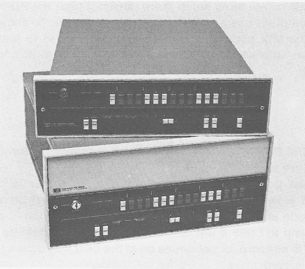 FIGURE 10.6 Two of the HP 21MX series of computers from Hewlett-Packard.
These small minicomputers are often used in dedicated applications.
(Photo courtesy of Hewlett-Packard Company.)
A number of internal registers are also used, including a program counter (P register), a memory address register (M register), and a memory data register (T register).
A special feature of the HP 2100 is that locations 0 and 1 of memory are the A and B registers, respectively. Thus, a LDA 1 will load the A register with the B register.
The instructions of the HP 2100 can be grouped into three classes of instructions:
Memory reference instructions are encoded as shown in Figure 10.8. Four bits are used for the opcode, giving 16 different memory reference instructions. Addressing of memory is accomplished by two techniques, indirection and paging. Bit 15 of the instruction specifies either direct (D/I = 0) or indirect (D/I = 1) addressing. If indirect addressing is specified, the address given in the instruction is not the address of the operand, but the address of the address of the operand. Since only 15 bits are needed for an address, and the word in the indirect address is 15 bits, the high-order bit of that word is again taken as a direct/indirect bit. Indirect addressing can occur to any number of levels, and continues until bit 15 of the word fetched from memory is zero. When bit 15 is zero, the remaining bits specify the address of the operand.
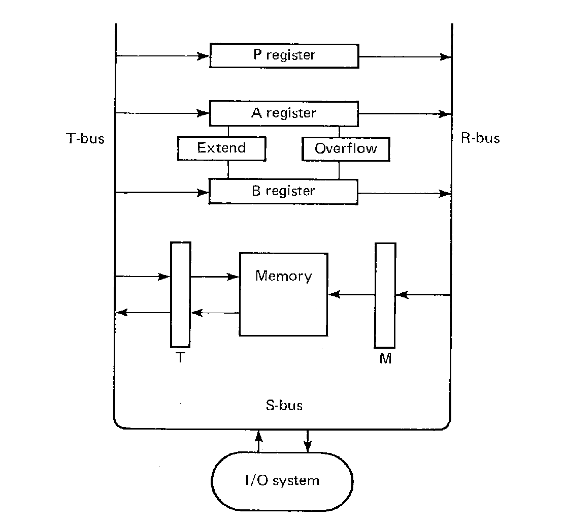 FIGURE 10.7 A block diagram of the HP 2100
computer. All registers are 16 bits, except the extend and
overflow bits, and the 15-bit M register.
Paging allows the 10 bits in the instruction to specify a 15-bit address. Bit 10 of a memory reference instruction specifies if the upper 5 bits of the address should be zero (Z/C = 0) or the same as the upper 5 bits of the program counter (Z/C = 1). This logically breaks memory up into 32 pages, each with 1024 words. The 1024 words on the zero page or the 1024 words on the current page can be accessed directly at any time. The remaining pages must be accessed indirectly.
 FIGURE 10.8 Memory reference instruction format for HP 2100.
The effective address calculation for the HP 2100 is thus as follows.
The instruction set is then (expressing the opcode as an octal number)
| 02 | AND | AND the contents of the effective address to the A register, leaving the results in the A register. | ||
| 04 | XOR | Exclusive-OR the contents of the effective address to the A register, leaving the results in the A register. | ||
| 06 | IOR | Inclusive-OR the contents of the effective address to the A register, leaving the results in the A register. | ||
| 03 | JSB | Jump to subroutine. Store the address of the next instruction in the effective address and jump to the effective address plus one. | ||
| 05 | JMP | Jump to the effective address. | ||
| 07 | ISZ | Add 1 to the contents of the effective address and store the sum back in the effective address. Skip the next instruction if the stored sum is zero. | ||
| 10 | ADA | Add the contents of the effective address to the A register. | ||
| 11 | ADB | Add the contents of the effective address to the B register. | ||
| 12 | CPA | Compare the contents of the effective address to the A register. Skip the next instruction if they are equal. | ||
| 13 | CPB | Compare the contents of the effective address to the B register. Skip the next instruction if they are equal. | ||
| 14 | LDA | Load the contents of the effective address into the A register. | ||
| 15 | LDB | Load the contents of the effective address into the B register. | ||
| 16 | STA | Store the contents of the A register into the effective address. | ||
| 17 | STB | Store the contents of the B register into the effective address. |
Notice that these instructions are similar to the instructions for the PDP-8. However, the extra bit in the opcode field has allowed us to add another register (the B register) and some additional instructions (the IOR, XOR, CPA, CPB). Also by including a load instruction, we no longer need a deposit and clear, but can use a standard store instruction.
The register reference instructions come in two groups: the shift-rotate group and the alter-skip group. These instructions are formed by combining subinstructions. The format of these instructions is shown in Figure 10.9. Bit 11 controls whether the A or B register is used. For the shift-rotate group, bits 8-6 and 2-0 are 3-bit shift and rotate fields. The shifts and rotates are
| Mnemonic | Bit Pattern | Meaning |
|---|---|---|
| | | |
| *LS | 000 | Shift left one bit, end off. |
| *RS | 001 | Shift right one bit, end off. |
| R*L | 010 | Rotate left one bit, circular. |
| R*R | 011 | Rotate right one bit, circular. |
| *LR | 100 | Shift left one bit, then zero sign bit. |
| ER* | 101 | Rotate right one bit register and Extend bit. Bit 0 into E; E into 15. |
| EL* | 110 | Rotate left one bit, register and Extend bit. Bit 15 into E; E into bit 0. |
| *LF | 111 | Rotate left four bits. |
The * is either A or B, depending upon which register is selected by bit 11. Since all of these combinations select some change on the selected register, a separate bit is used to disable or enable the selected shift. If the control bit disables the shift, then the register is not changed; the shift does not occur. (This provides a NOP if both shifts are disabled). Bit 9 is the disable/enable control bit for the shift/rotate of bits 8-6; bit 4 is the disable/enable control for bits 2-0.
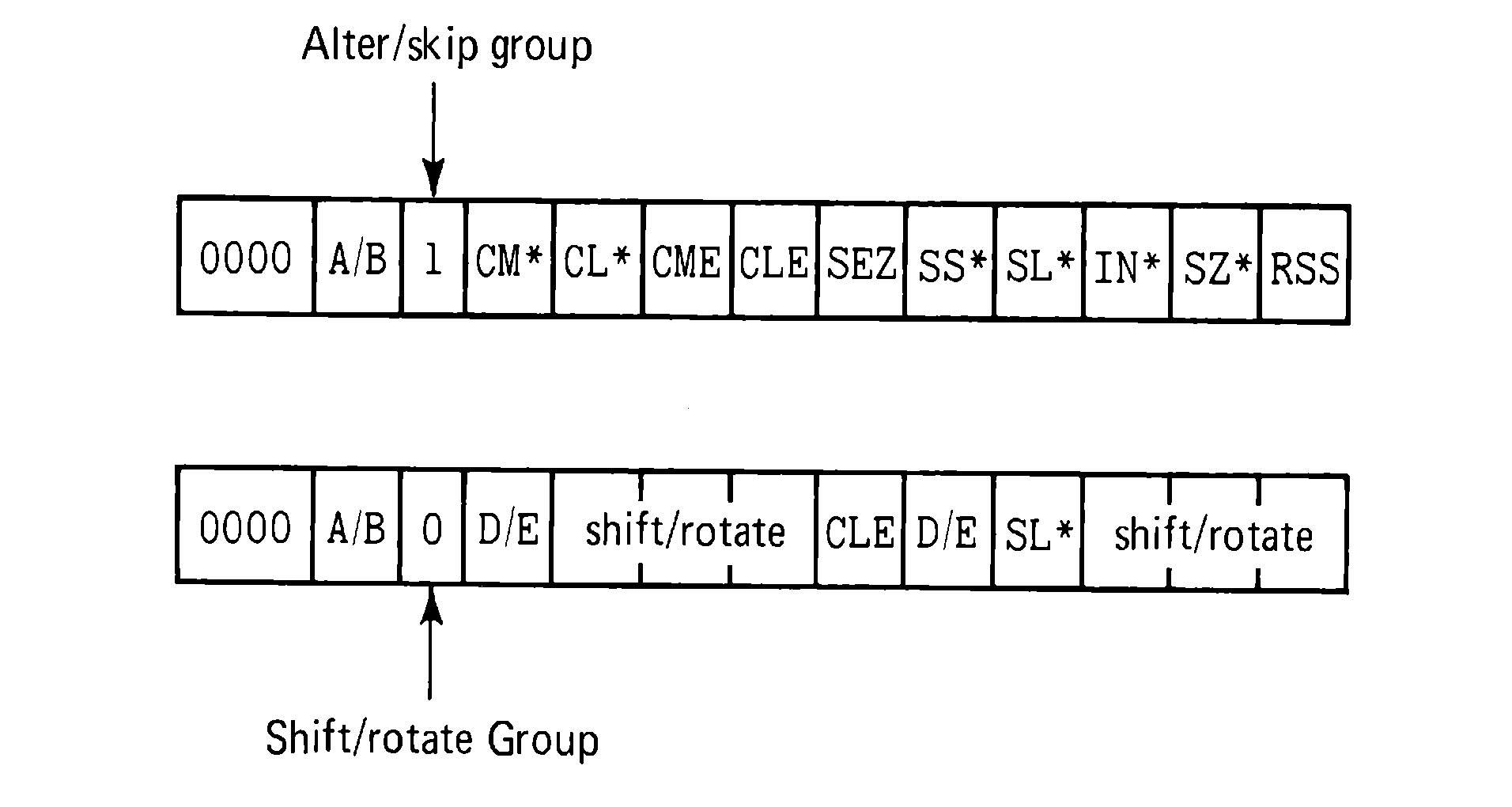 FIGURE 10.9 Alter/skip and shift/rotate instruction
formats for HP 2100.
Bit 5, if set to one, causes the Extend bit to be cleared; otherwise it is left alone. Bit 3, if set to one, will cause the CPU to skip the next instruction if the least significant bit (bit 0) of the selected register is zero; the next instruction is executed as normal if bit 3 is zero or bit 0 of the selected register is nonzero. These two functions (clear E; skip if low-order bit zero) occur after the shift function selected by bits 9, 8, 7, 6 and before the shift function of bits 4, 2, 1, 0.
These subinstructions can be combined according to the following:
| (Any Shift/Rotate), CLE, SL*, (Any Shift/Rotate) |
The alter-skip group provides the following subinstructions, where the * represents either A or B, as selected by bit 11.
| CL* | Clear register | |
| CM* | Complement register | |
| SEZ | Skip on E zero | |
| CLE | Clear E | |
| CME | Complement E | |
| SS* | Skip if register is positive | |
| SL* | Skip if low-order bit is zero | |
| IN* | Increment register | |
| SZ* | Skip if register is zero | |
| RSS | Reverse skip sense. |
| CL*, | CM*, | SEZ, | CLE, | CME, | SS*, | SL*, | IN*, | SZ*, | RSS |
The assembler for the HP 2100 is a three-pass assembler like the assembler for the PDP-8. The first pass creates the symbol table, the second the output loader code, and the third a program listing.
The input to the assembler is free-format, consisting of a label field, opcode field, operand field, and comment field, delimited by spaces. The label field is optional; it must start in column 1 if it is present. The operand field may be an expression formed from symbols, decimal numbers, or "*" (the location counter value). Expression operators are addition and subtraction. Octal numbers are indicated by using the letters as a suffix. Literals may also be used. Indirection is indicated by following the operand with a comma and the letter I, as
Pseudo-instructions for the HP assembler include ORG (to define the origin of a program or reset the location counter), END, EQU, DEC (to define a decimal constant), OCT (to define an octal constant), and BSS (to reserve storage locations). Pseudo-instructions also exist for creating relocatable programs with entry points (ENT), and external symbols (EXT). Primitive conditional assembly and some listing pseudo-instructions are also provided.
Programming for the HP 2100 is very similar to programming either the PDP-8 or MIX computers. The additional register allows some code to be simpler on the HP 2100 than on the PDP-8. The longer word length increases the range of numbers which can be represented, the number of opcodes, and the amount of memory which can be addressed. The major changes are in the I/O system.
Each I/O device has two bits to control I/O operations. One bit is called the control bit; the other is the flag bit. The setting of the control bit initiates an I/O operation; the control bit cannot be changed by the device. The flag bit is set by the I/O device when a transfer is complete. Normal I/O operation is to clear the flag and set the control bit to initiate the I/O operation. When the I/O device finishes the I/O operation, it sets the flag bit. Each device has its own interface card, with control and flag and buffer registers. Information is normally transferred between the A and B registers and the device interface buffer.
I/O instructions have four fields. The A/B bit selects either the A or B register; the H/C bit will clear the flag bit of the selected device if the H/C bit is one. The device field is a 6-bit field which indicates the selected I/O device. A 3-bit operation field specifies an I/O operation to be performed on the selected device. These are,
| Mnemonic | Bit pattern | Meaning | |
|---|---|---|---|
| | | | |
| HLT | 000 | Halt the computer | |
| STF,CLF | 001 | Clear or set the flag (bit 9 says which) | |
| SFC | 010 | Skip on flag clear | |
| SFS | 011 | Skip on flag set | |
| MI* | 100 | Inclusive-OR interface buffer to register | |
| LI* | 101 | Load interface buffer into register | |
| OT* | 110 | Output from register to interface buffer | |
| STC,CLC | 111 | Set or Clear (bit 11) the control bit |
 FIGURE 10.10 Input/output instruction format for HP 2100.
Input or output can be done under flag control using busy wait loops, as in MIX. For example, to output one character
Two major improvements were made over the PDP-8 I/O. In addition to the busy loop I/O technique illustrated above, the HP 2100 has an interrupt system. The PDP-8 had an interrupt system which would, when any device requested an interrupt, store the address of the next instruction is location 0, and begin execution at location 1. The interrupting device could be determined by polling.
The HP 2100 eliminates the need for polling by having a vectored interrupt system. Instead of all interrupts causing a forced transfer to a fixed address, each device on the HP 2100 interrupts to a different location. The device number indicates the address to interrupt to. Thus, device 20 interrupts to location 20; device 21 interrupts to location 21; and so on. The action which occurs when an interrupt occurs is somewhat different also. Instead of automatically executing a subroutine jump (as on the PDP-8), the contents of the interrupt location for the interrupting device is fetched and executed as an instruction. No registers are changed before the fetched instruction is executed. Typically, the instruction executed is a subroutine jump.
For example, if we have a JSB 300 in location 20, are executing the instruction at location 1734, and an interrupt request arrives from device 20, the execution proceeds as follows. The execution of the instruction at location 1734 continues until it is completed, since it had already begun. Interrupt requests are honored only between instructions, never in the middle of an instruction execution. The program counter is incremented to 1735. Now the computer pauses before fetching the instruction at 1735 to look for interrupt requests. Seeing a request from device 20, it fetches the contents of location 20, decodes it, and executes it (intending to continue at 1735 after this one instruction). The instruction at 20 is a jump to subroutine at location 300, so the program counter (with 1735 in it) is stored in location 300, and then reset to 301. Execution continues at location 301. Control can be returned to the interrupted program by an indirect jump through location 300.
Notice that, since each device interrupts to a different location, each device interrupt can be serviced immediately. There is no need to poll all the devices to determine which caused the interrupt. An additional feature of the HP interrupt system is its priority interrupt structure. On the PDP-8, the interrupt system is automatically turned off when an interrupt occurs. On the HP 2100, when an interrupt from device x is requested, interrupts from all higher numbered devices are disabled, but all lower numbered devices may still interrupt. Thus, a priority scheme is established where higher priority (lower device numbered) devices can interrupt lower priority (higher device numbered) devices. Generally, higher speed devices are given higher priority so that they will not have to wait for lower speed devices to be serviced before continuing.
An interrupt is requested anytime the interrupt system is on, and a flag is set. Setting the flag disables interrupt requests from lower priority devices. These requests are held pending. When the flag of a interrupting device is cleared, the next lower priority pending request becomes enabled and can cause a new interrupt for that device.
With a 6-bit device select field, up to 64 different device codes are possible. Some of these are used for special purposes. Device 0 is the interrupt system, device 1 is the overflow bit and switch register. Devices 4 and 5 are used to indicate interrupts caused by a power failure (4) or a parity error in memory (5).
The addition of a priority vectored interrupt system is one major feature of the HP 2100 I/O system. The other is the direct memory access (DMA) feature. High-speed I/O devices, such as disks, drums, and magnetic tapes, can sometimes transfer information faster than the computer can handle it if all information must go through the A or B register when being transferred between memory and the I/O device. At best, because of instruction fetches, incrementing pointers, the lack of index registers, comparisons, and such, only one word every seven memory cycles can be input or output. Even this takes all available CPU time. To change this situation, a special "device" is available on the HP 2100 which allows DMA transfer between memory and a high speed I/O device which bypasses the CPU completely.
A DMA processor is a special purpose processor which is built for one purpose and one purpose only, to transfer information between memory and an I/O device. To start a DMA transfer, the DMA device is told (a) which device is involved, (b) whether the transfer is an input or an output, (c) the address in memory for the transferred words, and (d) the number of words. The DMA processor then supervises fetching words from memory and sending them to the I/O device, or vice-versa, as fast as the I/O device and memory can handle them. This continues until all words are transferred (or an error occurs). While this is going on, the CPU may continue computing. (The I/O for MIX consists of DMA transfers). The I/O can proceed at the speed of the I/O device. The DMA device does cycle-stealing by using memory read-write cycles as necessary when the CPU is not using memory. If both the CPU and DMA want a word from memory at the same time, one of them must wait, and it is generally the CPU which does the waiting.
The HP 2100 is a considerable improvement over the PDP-8. It has a longer word length, additional register, more instructions, and more sophisticated I/O system, including a priority, vectored interrupt system and DMA transfers. These additional features are not free, however. A minimal HP 2100 system with CPU and 4K of memory costs around $6,000. As with the PDP-8, the best source of further information is the manufacturer. Hewlett-Packard publishes the "Pocket Guide to the 2100 Computer," a manual which covers the basic hardware for the HP 2100 as well as the assembler, Fortran, Basic, and a simple operating system.
The PDP-11, first announced in 1969, is not just one computer, but has developed over the years into a family of computers. All PDP-11 computers have the same instruction set. The various models may have different options available, are manufactured from different hardware technologies, use memories of different speeds, and cost different amounts. The models vary from the LSI-11 (less than $1,000), 11/04, and 11/10, at the small, slow, and cheap end, through the medium size 11/40, and 11/45 to the moderately fast 11/70 ($55,000), the top of the line. The 11/04 can have from 4K to 28K words of memory and is used mainly for process control and laboratory use. The 11/70 on the other hand can have up to 2 million words of memory and is used as a general purpose computing machine.
Memory for the PDP-11 is designed to handle the desire to access both words and bytes. Memory consists of 16-bit words, each of which is composed of two 8-bit bytes, an upper (high-order) and lower (low-order) byte. Memory is byte-addressable, meaning that each byte has its own unique address. Words are addressed by the address of the low-order byte. Thus, addresses of sequential memory locations are 0, 2, 4, 6, 8, and so on. The word at location n (where n is an even number) is composed of the bytes with addresses n and n + 1. Addresses are 16 bits.
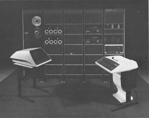 FIGURE 10.11 A PDP-11 computer system. The processor
in this system is the PDP-11/35. Also shown is a set of
peripherals including magnetic tape, disks, cassette tapes, paper
tape reader, CRT, and printer. (Photo courtesy of Digital
Equipment Corporation.)
Each byte can hold an integer from 0 to 255 which can be either a small integer or a character code. The ASCII character code is most commonly used. Each 16-bit word can be either two characters or an integer number. Instructions treat 16-bit integers as either unsigned integers or signed two's complement numbers. Floating point numbers are represented by either two words (with sign, 8-bit excess 128 exponent, and 23-bit fraction) or four words (with sign, 8-bit excess 128 exponent, and 55-bit fraction). Floating point numbers are always normalized, so the leading one bit just after the binary point in the fraction is not stored.
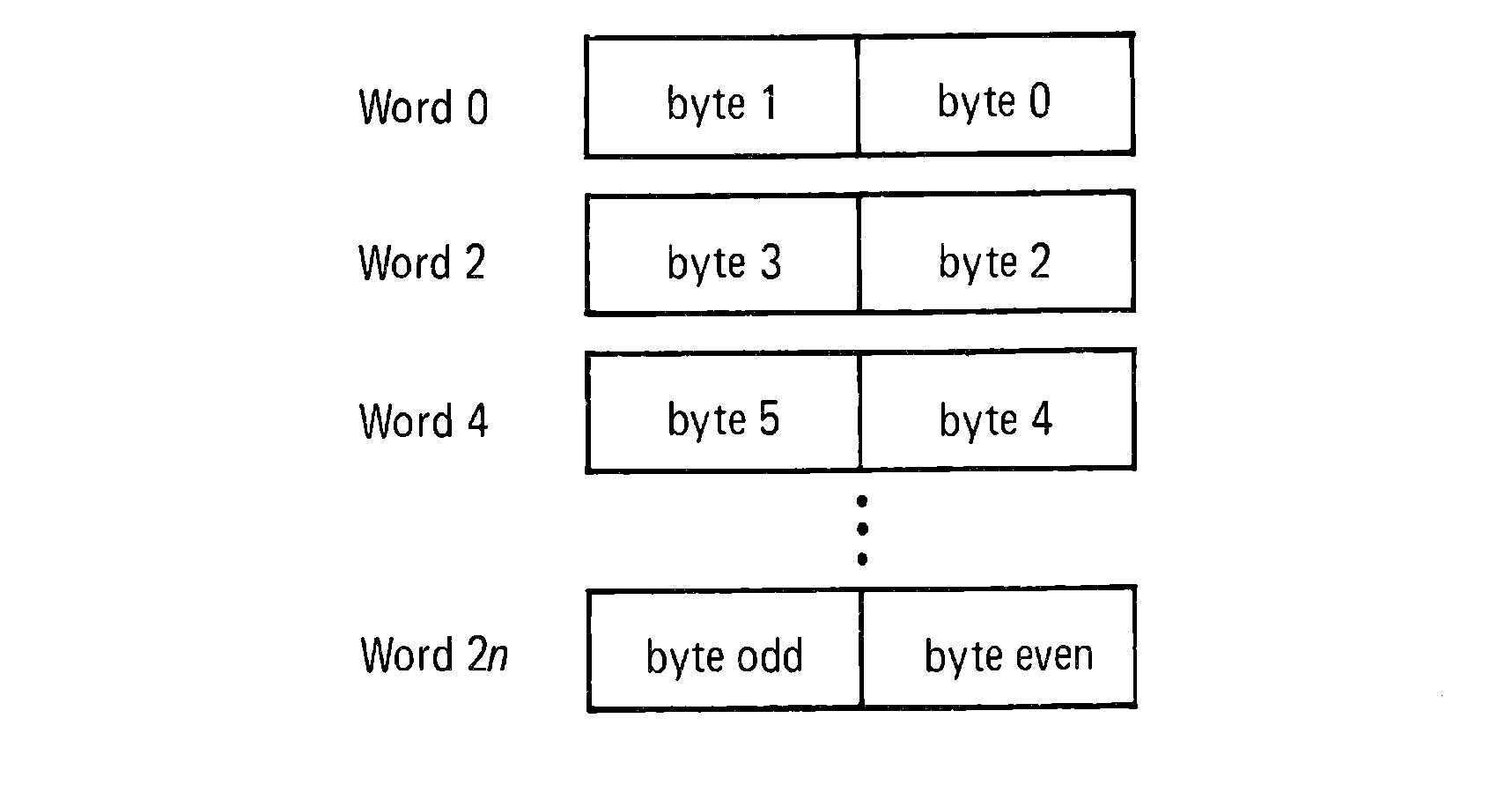 FIGURE 10.12 Memory on the PDP-11 is byte-addressable. Words are two
bytes, so word addresses are even.
The PDP-11 has eight (or seven or six) 16-bit general purpose registers. A general purpose register can be used as either an accumulator or an index register, or both, or anything else that a 16-bit register can be used as. The vagueness over the number of registers comes from the fact that two of these registers are used for special purposes: register 7 is the program counter, and register 6 is used as a stack pointer. Thus, although the instructions allow registers 6 and 7 to be used as any other register, they are normally not used as general purpose registers.
In addition to the general purpose registers, a collection of bits indicate the status of overflow, carry, and comparisons. These bits are grouped together and collectively called the condition code. The condition code consists of four bits (N, Z, V, C) which roughly are used to indicate the following information about the last CPU operation,
| Z | = | 1 | if the result was zero. |
| N | = | 1 | if the result was negative. |
| C | = | 1 | if a carry out of the high-order bit resulted. |
| V | = | 1 | if there was an arithmetic overflow. |
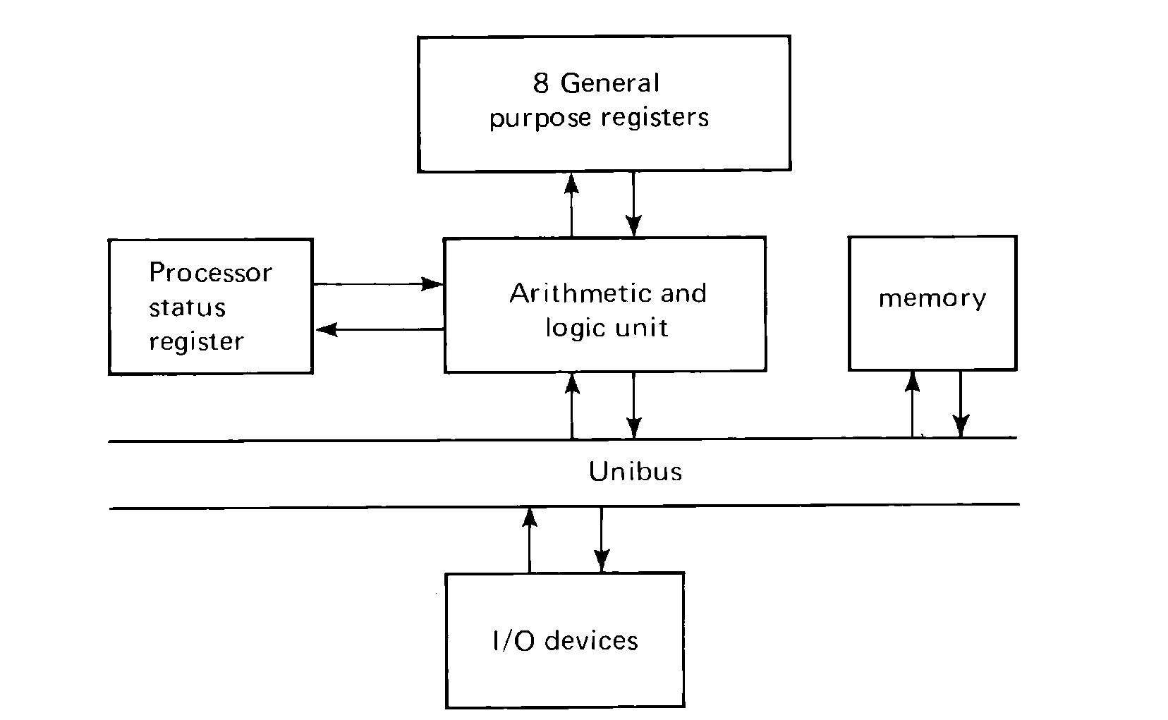 FIGURE 10.13 Block structure of a PDP-11. The CPU,
memory, and all I/O devices communicate by using the UNIBUS. The
UNIBUS is a set of 56 wires which allow data and addresses to be
transmitted between any two devices, memories, or CPUs on the
bus.
The PDP-11 has a very rich instruction set, which makes it that much more difficult to describe, and that much easier to program when the entire instruction set is understood. The instructions can be grouped into the following categories
The double and single operand instructions may address memory. For the double operand instructions, two addresses need to be specified; for single operand instructions, only one address need be specified. Since memory addresses are 16 bits long, how can one instruction specify two 16-bit addresses in one 16-bit word? The answer is that it often does not, but the solution to the problem is actually somewhat more complex.
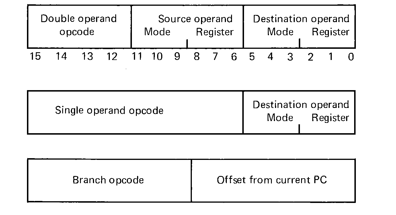 FIGURE 10.14 Instruction formats for the PDP-11.
Instructions sometimes specify addresses in different ways. On the MIX computer, addresses could be direct, indexed, indirect, or combinations of these. Each different way of specifying the address is an addressing mode. The PDP-11 has eight addressing modes. A register is used with each addressing mode. Each address is thus six bits long, three bits to specify one of eight modes and three bits to specify one of the eight general purpose registers. These eight modes and their assembler syntax are
| Assembler syntax | Numeric mode | Meaning |
|---|---|---|
| | | |
| Rn | 0 | General purpose register n. |
| (Rn) | 1 | The contents of register n is the address of the operand. |
| (Rn)+ | 2 | The contents of register n is the address of the operand, and after the contents is used as an address it is incremented (auto-increment). |
| @(Rn)+ | 3 | Indirect auto-increment. |
| -(Rn) | 4 | The contents of register n is decremented and then used as the address of the operand (auto-decrement). |
| @-(Rn) | 5 | Indirect auto-decrement. |
| X(Rn) | 6 | The contents of the next word in memory (X) are added to the contents of register n to yield the address of the operand (indexing). |
| @X(Rn) | 7 | Indirection after indexing. |
These eight modes allow for a great flexibility in programming. Operands can be registers, or pointed at by registers, or pointed at by the address in words pointed at by registers. In addition pointer registers can be incremented or decremented automatically to allow operations on tables, arrays, or character strings. The auto-decrement before and the auto-increment after were specifically designed for use with stacks. Using the program counter (register 7) in mode 6 allows addresses to be specified as program counter relative. The advantage of this mode is that the instruction need not be changed if the program is loaded in a different set of locations (relocated). Code with this feature is called position independent code.
One major group of instructions is the double operand instruction group. These instructions have two operands: a source and a destination. The high-order bit indicates if the operands are bytes or words. The source and destination fields each specify one of the addressing modes listed above and a register. The opcodes are
| MOV | 1 | Copy the contents of the source to the destination. | ||
| CMP | 2 | Compare the source and destination and set the condition code. | ||
| BIT | 3 | AND the source and destination and set the condition code. Do not change either the source or destination. | ||
| BIC | 4 | Clear the bits in the destination which correspond to one bits in the source. | ||
| BIS | 5 | Set the bits in the destination that correspond to one bits in the source. | ||
| ADD/SUB | 6 | Add or subtract (bit 15 says which) the contents of the source to the contents of the destination, storing the result back in the destination. |
The single operand instructions use the same address modes as the double operand instructions but only operate on one operand. Most of these instructions are instructions which, on the PDP-8 or HP 2 100, use one of the registers as an operand. On the PDP-11, one of the registers, or any memory location, can be the operand for the instruction.
| CLR | Clear. Set the contents of the operand to zero. | |
| COM | Complement the contents of the operand. | |
| INC | Increment by 1 the contents of the operand. | |
| DEC | Decrement by 1 the contents of the operand. | |
| NEG | Negate the operand (complement and add one). | |
| TST | Test the contents of the operand and set the condition code. | |
| ASR | Arithmetic shift right. | |
| ASL | Arithmetic shift left. | |
| ROR | Rotate right. | |
| ROL | Rotate left. |
| ADC | Add carry. | |
| SBC | Subtract carry. |
All the test and compare instructions set the condition code. To jump on the outcome of a test, a branch (or jump) instruction is used. Separate branch instructions are available for almost every interesting condition code value. The format of the jump instruction includes five bits which determine the test to be used to determine if a jump should take place (branch on equal, not equal, plus, minus, and so on). The address to jump to is defined by an 8-bit offset (interpreted as an 8-bit signed two's complement number) plus the program counter. Thus, a branch instruction can transfer control up to 128 words backwards, or 127 words forwards. All branches are automatically position independent.
For longer transfers of control, the JMP instruction is used. Both the JMP and JSR (jump to subroutine) instructions allow their operands to be specified in any of the PDP-11 addressing modes. The JSR also specifies a register. The return address is put in the register and the previous contents of the register are pushed onto the stack pointed at by register 6. An RTS (return from subroutine) instruction reverses the operations, jumping to the address contained in a register and reloading the register from the top of the stack.
This last classification includes HALT and WAIT (wait for an interrupt) instructions as well as an entire set of instructions for setting or clearing the condition code bits. Additional instructions are used mainly with operating systems to cause and return from interrupts.
The assembly language for the PDP-11 is more similar to the assembly language for the PDP-8 than MIXAL. An assembly language statement still has four fields: label, opcode, operand, and comment. Input is free-format. A label is followed by a colon (:). Comments are preceded by a semicolon (;). Operand formats depend upon the type of opcode and the mode of the addressing. Double operand instructions are of the form
The pseudo-instructions for the PDP-11 are distinguished from machine instructions by all starting with a period. The assembler includes the normal pseudo-instructions
| .GLOBL | Declares each symbol on its operand list to be either an entry point or an external. The assembler knows which, since entry points will be defined in this program, and externals will not. | |
| .WORD | Acts like a CON for full word values | |
| .BYTE | Acts like a CON for bytes. | |
| .ASCII | Defines an ASCII character coded string. | |
| .EVEN | Assures that the location counter is even (so that it addresses a word). | |
| = | The equal sign is used for an EQU pseudo-instruction. |
The PDP-11 has no I/O instructions. I/O is performed in a manner which allows the normal instruction set to do all necessary I/O functions. This is done by assigning all I/O devices, not a device number, but an address, or set of addresses in memory. All I/O device control registers, buffer registers, and status registers are assigned addresses in the PDP-11. (In the HP 2100, the A and B registers were assigned addresses 0 and 1 in memory. The registers were not really in memory, but simply could be accessed by the addresses 0 and 1.) On the PDP-11, the upper 4K words of memory, from addresses 160000 to 177777 (octal) are reserved for I/O device addresses.
For example, if a PDP-11 has a card reader attached, that card reader has two registers associated with it, a control register and a data register. The control register will have address 177160, and the data register, address 177162. A line printer will have addresses 177514 (control and status) and 177516 (data). An RF11 disk uses the addresses from 177400 to 177416 for various status registers, word counts, track address registers, memory addresses, and so on.
I/O is performed differently for each device. For simple devices, however the interface is generally provided by two registers: a control register and a data register. For output a character is put in the data register (using the MOV or MOVE instructions). Then a bit is set in the control registers (using the BIS instruction). When a bit is cleared by the device, the output is complete. For higher-speed devices, DMA transfers are made.
The PDP-11 has a priority vectored interrupt system. Two types of interrupts can occur: I/O interrupts and traps. A trap is an interrupt caused by the CPU. In the PDP-11, traps can occur for many reasons, including illegal opcodes, referencing nonexistent memory, using an odd address to fetch word data or instructions, power failure, and even some instructions. Traps cannot be turned off; they will always cause an interrupt. I/O interrupts will only be recognized when the priority of the I/O device exceeds the priority of the CPU.
The CPU priority is kept with the condition code bits in a special register called the processor status. The processor priority is a three-bit number, allowing eight priority levels in the PDP-11. Each device has its own (fixed) three-bit priority. An interrupt request from a device will be recognized if the device priority is greater than the current CPU priority.
Interrupt processing on the PDP-11 is more complex than on the HP 2100. Notice that there are no device numbers and that sequential memory addresses refer to single bytes, while addresses are two bytes long and instructions may be several words long. On the PDP-11, each device is assigned an interrupt location. Interrupt locations are in low memory, starting at address 4 and counting at 4-byte intervals up to address 192. Each interrupt location is two words (4 bytes) and consists of a new processor status (priority and condition code) and an address. The address is the address where control should be transferred when an interrupt occurs. When an interrupt occurs, the current processor status and program counter are pushed onto the stack pointed to by register 6. Then a new processor status and a new value for the program counter are loaded from the interrupt vector, in low core, for the interrupting device. Execution now continues at the new program counter. A special instruction, RTI (Return from Interrupt) is used to reload the old processor status and program counter when the interrupt processing is over.
The PDP-11 has been a highly successful computer. Many people think that it is one of the better designed computers in years, that it is easy to program and easy to use. A number of relatively sophisticated programming techniques (stacks, reentrant code, position independent code) can be routinely used on the PDP-11. The I/O system has been designed to allow I/O programming to be a natural extension of ordinary programming, while the interrupt system provides a fast means of handling I/O to achieve maximum response to external I/O events.
Manuals published by Digital Equipment Corporation about the PDP-11 include processor handbooks for each of the models of the PDP-11. Separate handbooks describe available software and peripheral devices. The PDP-11 is also discussed in Gear (1974), Eckhouse (1975), and Stone and Siewiorek (1975), which use the PDP-11 as an example machine to teach assembly language programming in the same way we have used the MIX computer.
The IBM system 360 and system 370 line of computers is probably the most important computer system today, and no description of computer systems would be complete without including these machines. The 360 was announced in 1964, and is one of the first third-generation computers, using solid state circuitry with a low level of integration. The range of machines was an attempt to satisfy all customers with one basic architecture. This strategy has been successful for the most part.
The 370 series was brought out in 1970 to replace the aging 360 machines by newer computers with a compatible instruction set, but implemented in newer technology to give faster internal performance, increased reliability, and extended capabilities in some areas. For purposes of our discussion, the 360 and 370 computers are identical. Most 360s have been replaced by 370s by now, so we will refer to the IBM 370. A small 370/115 system will cost about $250,000, while a 370/168 can cost as much as $5,000,000.
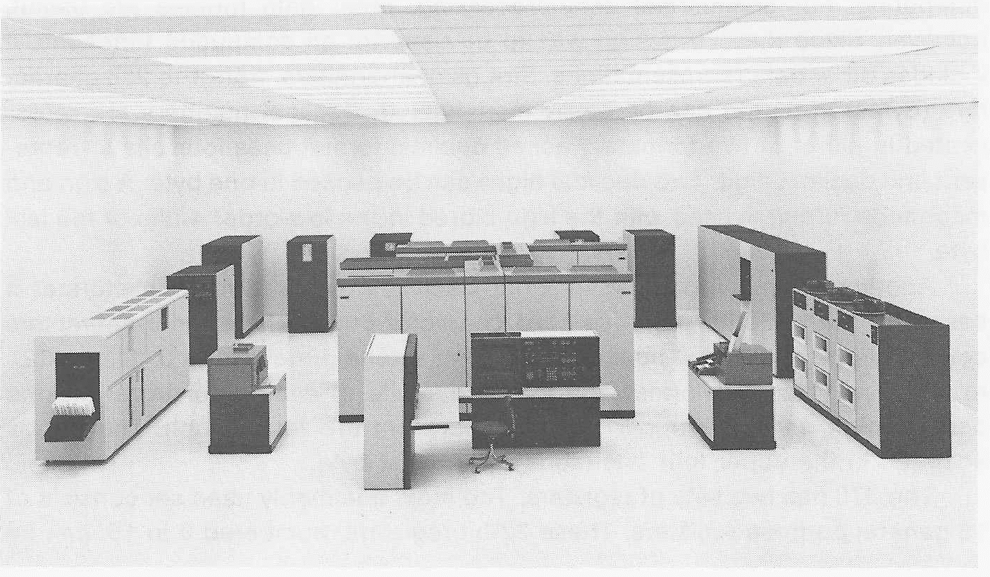 FIGURE 10.15 An IBM Model 168. One of the most powerful computers
available from IBM is shown here with a complete set of peripheral devices.
(Photo courtesy of IBM Corporation.)
As with the PDP-11, memory in the 370 is byte addressable. Memory is composed of 8-bit bytes, and memory size is generally quoted in units of bytes, not words. 370 systems have from a low of 64 kilo-bytes to a maximum of 16,384 kilo-bytes (16 mega-bytes) of memory. Each byte can hold an integer from 0 to 255, or one EBCDIC character.
Although memory is byte-addressable, it is generally used in larger quantities. A word on the 370 is 32 bits (4 bytes). Since memory is byte addressable, word addresses are all multiples of 4 (0, 4, 8, 12, 16, …). In addition, memory can be accessed by half-words (16 bits, 2 bytes, addresses multiples of 2), or double-words (64 bits, 8 bytes, addresses multiples of 8). Memory addresses are 24 bits long, allowing up to 16 mega-bytes of memory.
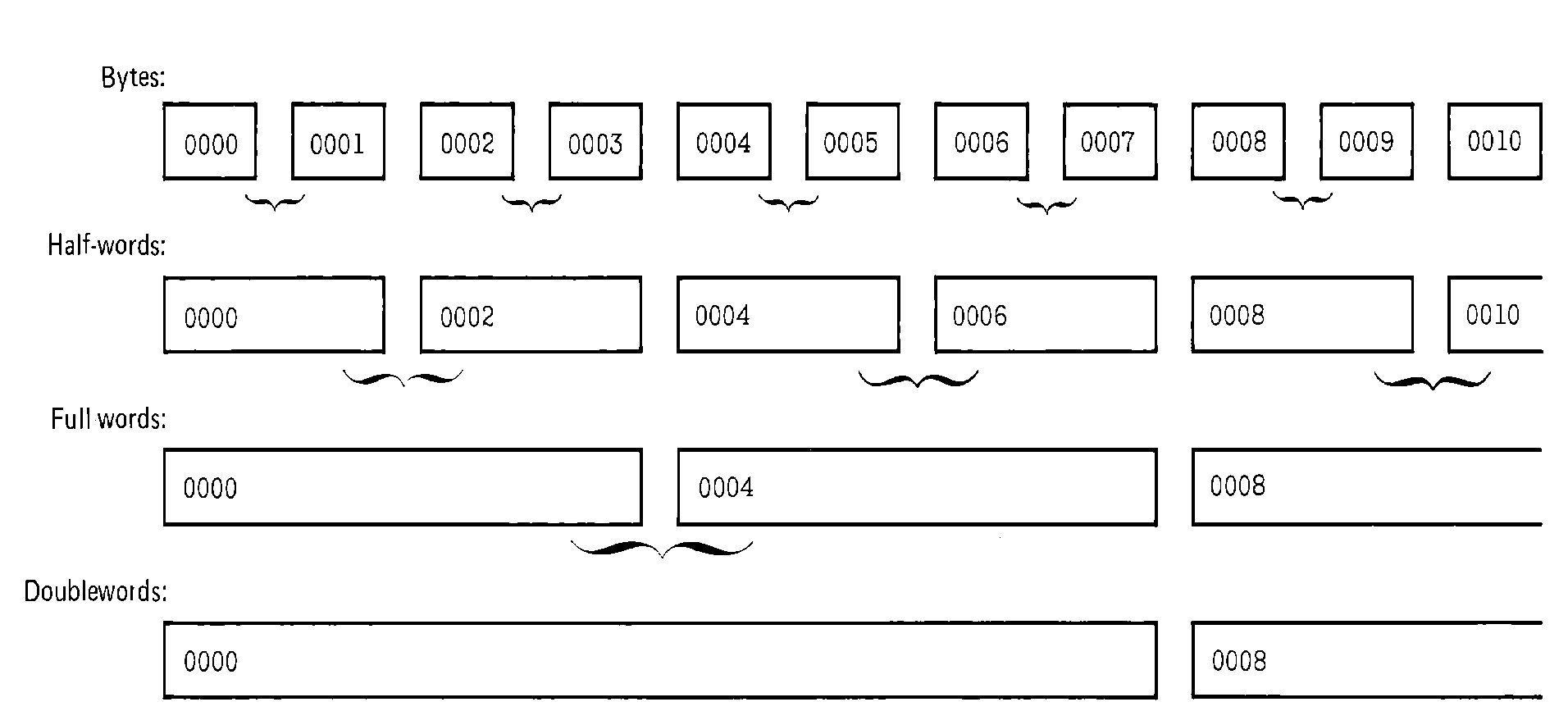 FIGURE 10.16 Organization of bytes, half-words,
full-words, and double-words in main storage of the IBM 370.
Number representation schemes on the 370 are many. The basic representation is two's complement integer. This representation can be used in a half-word or fullword memory unit. Bytes are treated as unsigned integers.
Floating point numbers in fullword memory units are stored as sign and magnitude numbers with a 7-bit excess-64 base 16 biased exponent, and a 24-bit fraction. A long floating point form increases the precision of the number to a 56-bit fraction. There is even an extended precision format which gives a 112-bit fraction (about 34 decimal places of accuracy).
The integer and floating point data representations on the 370 computers are normally found on general purpose computers. The integer format is used for counters and pointers. Floating point numbers are generally used in scientific computing. For commercial data processing, other data formats are useful, however. Since the 370 design was to be used for all computing functions, it includes other data representations. Strings of characters, from 1 to 256 characters (bytes) in length can be easily manipulated. Decimal numbers are represented in either of two formats. Packed decimal format uses four bits to represent one decimal digit. Two decimal digits can be packed in one byte. A sign and magnitude format is used with the sign stored in the low-order 4 bits of the last byte.
Another decimal format is the zoned decimal number format. This format is based on the Hollerith punched card character code, where most characters consist of one of the digit punches (0-9) and a zone punch (rows 0, 11, and 12). In the zoned decimal format, the lower four bits of each byte represent one decimal digit, while the upper four bits represent the zone punch. The sign is encoded in the upper four bits (zone) of the last byte.
 FIGURE 10.17 Representation of
decimal numbers on the IBM 370 is in two formats, packed and zoned.
The 370 has two sets of registers. The most commonly used set consists of 16 general purpose registers. These 32-bit registers, numbered 0 to 15, can be used as accumulators, index registers, pointers, and so forth. In addition, four 64-bit floating point registers (numbered 0, 2, 4, and 6) are used for floating point operations. Separate instructions control the use of the floating point and general purpose registers.
In addition to the general purpose and floating point registers, the 370 has a program counter (called the instruction address) and a condition code. These, along with other information, are stored in a program status word (PSW). The other information in the PSW deals mainly with interrupt enabling and disabling.
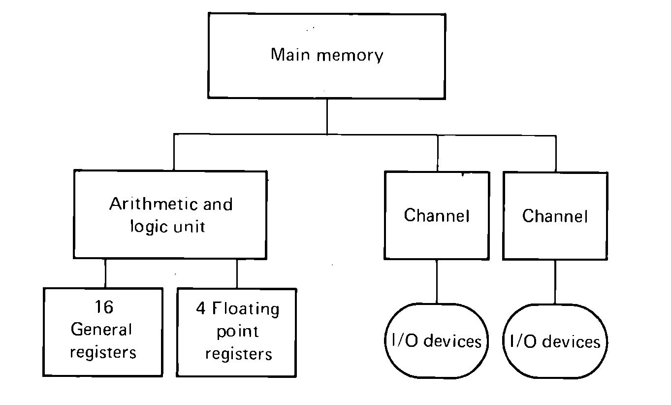 FIGURE 10.18 Block structure of an
IBM 360 or 370. Channels are special-purpose processors for performing
input and output from memory.
The designers of the 360 and 370 were faced with the same problem that other designers have: how to provide the largest set of useful instructions encoded into the least number of bits. This problem was solved in several ways.
First, an 8-bit opcode is used, providing up to 256 different instruction opcodes. In addition, different types of instructions are provided. Some instructions operate only on registers, others between memory and registers, still others between memory and memory. Since only 4 bits are needed to specify a register, and 24 bits are needed for a memory address, this results in instructions of varying length. Register-to-register instructions need only specify an opcode (one byte) and two registers (one byte), while memory-to-memory instructions take six bytes for opcode and two addresses.
Another technique used was to group the instructions according to function. Not all models include all instructions. For example, the small commercial models may not include the Floating Point Instructions, while the larger scientific machines may not include the decimal instructions. If these instructions are used on machines which are not equipped for them, they are treated as illegal instructions and a trap occurs.
The major problem for a computer designer is memory accessing. Since the 360/370 design was to be good for many years, it was designed with very large memory addresses, 24 bits. (Even so, some models have been modified to allow 32-bit addresses.) But if two 24-bit addresses are stored in an instruction, the instructions become very long. And, since few computer centers would have the funds to buy the entire 16 mega-bytes of memory, most of the addresses which were used would have up to 8 bits of leading zeros. Even if the maximum memory existed, few programs would need to use all of it.
These two contradictory goals (large address space, and short instructions) were solved by using a base-displacement addressing technique. All addresses are described by 16 bits: a 4-bit base register and a 12-bit displacement. The address is computed by adding the contents of the selected register to the displacement. The lower 24 bits of this sum is the memory address. (The extension to 32-bit addresses is obvious.)
Register 0 cannot be used as a base register. If register 0 is used as the base register, the contents of the register are ignored and a zero is used as the base address. Thus, the lower 4096 bytes may be accessed directly without setting a base register. To access any other byte in memory, it is necessary to use at least one register as a base register. Most commonly, one or two registers are used as base registers to allow access to instructions in the current subroutine (needed for local variable accessing and jump addresses), and one or two are used for accessing global variables, arrays, tables, and other data structures. Notice that this can reduce the number of generally available registers from 16 to 12 or 13.
The instruction formats for the different instructions are shown in Figure 10.19. The RX-formatted instructions, which include most memory reference instructions, allow indexing by any general register (except register 0) in addition to the base-displacement address calculation. Although we cannot discuss all of the instructions, here are some of them.
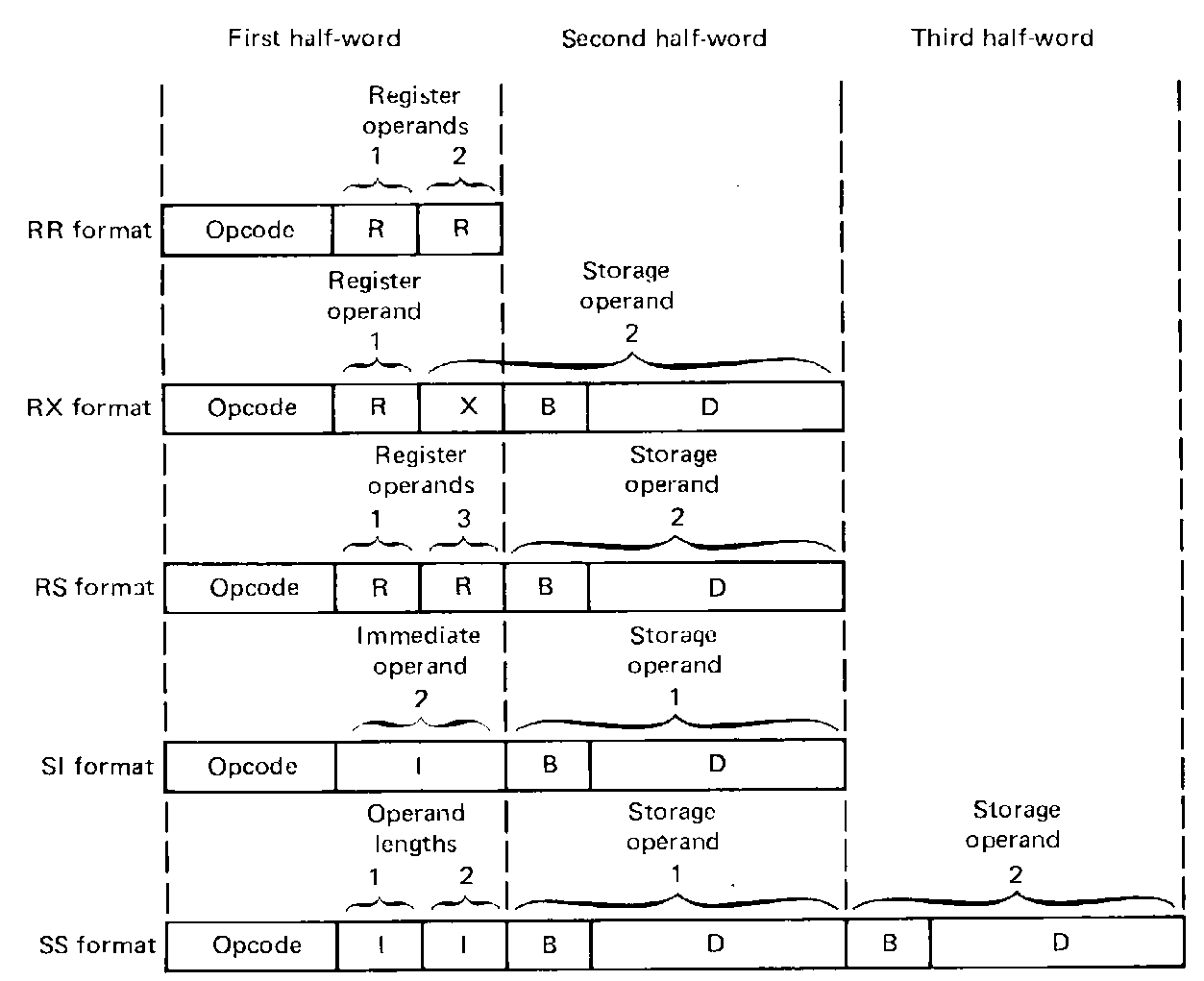 FIGURE 10.19 The five basic
instruction formats of the IBM 360 and 370.
The load instructions copy information from memory to the registers. Loading instructions allow the general registers to be loaded with another register (LR), a fullword (L), a half-word with sign extension (LH), and load an immediate quantity, like an ENTA (LA). Additional loads between registers allow load complement (LCR), load and test, setting the condition code (LTR), load positive (LPR), and load negative (LNR). Multiple registers can be loaded from memory at once (LM), allowing all general purpose registers to be loaded with one instruction. Similar instructions allow the floating point registers to be loaded, single or double precision, from memory or a register, positive, negative, tested or rounded.
Storing can be done by character (STC), halfword (STH), fullword (ST), or multiple registers (STM).
Arithmetic operations can be between registers or memory, fullword or halfword, and include addition (A, AR, AH, AL), subtraction (S, SR, SH, SL), multiplication (M, MR, MH), division (D, DR), and comparisons (C, CR, CH, CL, CLR, CLI). Multiplication and division involve double-length integers and so need double-length registers. This is done by grouping even and odd registers together as even-odd pairs. Register 0 is paired with register 1, register 2 with register 3, and so on. The comparison instructions set the condition code. Floating point arithmetic instructions operate on long or short floating point numbers in the floating point registers.
Jump instructions (called branch instructions) allow jumps to any address in memory on any setting of the condition code. Branch instructions also can be used to increment a register, compare against another register and branch if greater (BXH), or branch if less than or equal (BXLE), or decrement and branch if nonzero (BC, BCR). Subroutine jumps are made by a branch and link (BAL) instruction which puts the return address in a register.
Logical AND, logical OR and exclusive-OR instructions can be used on the general purpose registers for masking, as can a set of left or right, single or double (even-odd pairs), end-off shifts by any number of bits (0 to 63).
Decimal instructions all operate directly on numbers stored in memory and allow addition, subtraction, multiplication, division, and comparisons as well as instructions for converting between binary and packed decimal, and between packed decimal and zoned decimal. Fancy editing instructions allow leading zero suppression, check protection, and addition of commas and periods in decimal numbers for output.
Character strings can be manipulated by instructions which copy strings of bytes from memory to memory, that translate from one character code to another, or that search for particular characters.
The assembly language for the 370 is similar to the other assembly languages we have seen, but larger. The large number of different instructions, instruction formats, and data representations all make the assembler a very complex program. There are, in fact, at least six assemblers for the 370 assembly language, ranging from a two-pass load-and-go assembler to a four-pass assembler.
The basic assembly language statement format is the same as for a free-format MIXAL program. An optional label (up to eight characters, starting with a letter) may start in column one. The opcode field may be any of the symbolic mnemonic opcodes for 370 instructions, an assembler pseudo-instruction, or a macro call. The operand field format depends upon the opcode. The operand field may be followed by a comment field. All fields are separated by blanks. An asterisk in column 1 indicates a comment card.
One of the major problems in writing 370 programs is addressing. The base-displacement form of address calculation is a good hardware design but requires that the machine language programmer constantly calculate displacements. This is solved in assembly language by maintaining a base register table in the assembler. Whenever a symbol is used in an operand field where base-displacement in needed, the assembler searches the base register table for the base register closest to the symbol. The displacement from this base register is calculated, and code is generated using this displacement and base register. Entries are added to the base register table by the USING pseudo-instruction. It has the format
Other pseudo-operations include EQU, DC (a complex version of the CON statement), DS (a BSS statement), ENTRY and EXTRN (for relocatable programs), ORG, MACRO and MEND, listing control (define a title, start a new page, space), and many others.
The 370 assembly language, particularly its macro and conditional assembly features, is very powerful. A truly excellent programmer can write very sophisticated programs in 370 assembly language. The rest of us tend to ignore a large number of these features.
Six classes of interrupts can occur in the 370. These are I/O, external (an interrupt from a clock or power failure), program (illegal opcode, addressing error, illegal data, overflow or underflow, or translation errors), supervisor call (a special instruction to allow programs to communicate with the operating system), machine check (hardware failure) and restart (operator pushes the restart button on the console). Each type of interrupt has two doublewords assigned to it in low core. When an interrupt occurs, a new PSW is loaded from the first doubleword assigned to this type of interrupt; the old PSW is saved in the other doubleword (old PSW).
Each type of interrupt has a priority associated with it. If two interrupts are requested at the same time, the higher priority request takes precedence. In addition, four bits in the PSW allow I/O, external, machine check, and program interrupts to be enabled or disabled separately. Supervisor calls and restart interrupts are always possible.
Another field in the PSW records information on the specific interrupt which occurred. The device number and channel number are stored for I/O interrupts. In addition, the length of the last instruction is stored in the PSW to allow the computer to "back up" and try again if need be.
The I/O system of the 370 is quite sophisticated. All I/O is done directly to memory. This requires a processor, as on the HP 2100 and PDP-11, to control the transfer of information between the I/O devices and memory, to count the number of words transferred, and to keep track of the address where each word should go. On the HP 2100 and PDP-11, this was a relatively simple special-purpose processor. On the 370, this processor is more complex. It is called a channel. A channel on the 370 is a special purpose computer which can execute channel programs.
Channel programs, like CPU programs, are made up of instructions. The channel, after initiation by the CPU, executes a channel program by executing each instruction in the channel program, one after another. The channel program is stored in main memory along with normal CPU programs. The channel fetches each instruction from memory as necessary. The CPU initiates I/O activity by starting a channel with a Start I/O (SIO) instruction. When an SIO instruction is executed, the addressed channel loads the address of the first instruction in its channel program from location 72 in memory, and starts to execute its channel program. The CPU continues to execute programs independent of channel activity. Two other instructions, Test I/O (TIO) and Halt I/O (HIO), can be used by the CPU to interact with a channel.
A channel is a special purpose processor. Since it is meant to do I/O and nothing else, it does not need arithmetic instructions or conditional instructions or similar instructions which are necessary for computation. Each instruction to a channel is called a channel command word (CCW) and is a doubleword (see Figure 10.20). The fields of a CCW are its command code (read, write, read backwards, sense, control, and jump), a memory address of the memory buffer for the I/O transfer, a count of the number of bytes to transfer, and a set of flag bits. The flags contain various options including one to not store data during reads, to request an interrupt after each CCW (instead of only after the entire program is completed or an error occurs), and a chain bit. The chain bit in a channel command word is the opposite of a halt bit. As long as the chain bit in a CCW is on, the channel processor will continue to fetch the next doubleword in memory as a new CCW when the current CCW is completely executed. The first CCW which is encountered with a zero chain bit causes the channel processor to stop and request an interrupt of the CPU.
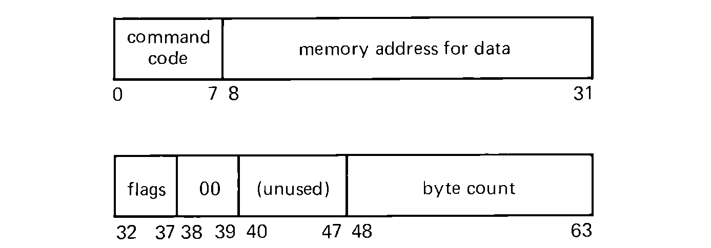 FIGURE 10.20 Channel command word format. The flags field
includes a chain bit.
There are several different kinds of channels available. Multiplexor channels are used for slow-speed devices, while selector channels are used for high-speed devices. Channels, with their direct memory access and ability to execute relatively simple sequences of I/O actions, relieve the CPU of the need to keep complete track of all activity itself, just as a secretary allows an executive to be more effective by taking over some of the routine work.
"IBM System/370 Principles of Operation" (IBM Order number GA22-7000) is the definitive reference on the 370 computers, while "IBM System/370 System Summary" (IBM Order number GA22-7001) gives a good overview of the different models, their features, and their peripherals. Several textbooks use the 360 and 370 computers to teach assembly language programming, including Struble (1975).
The B5000, announced by Burroughs in 1961, is a radical departure from the architecture of most computers. Most computers are register-oriented, from the programmer's point of view, while the Burroughs' computers are stack-oriented (see Section 4.5). The B5000 was the first of this line of computers. The B5500 (1965) was a second edition which solved some of the problems of the B5000. More recent computer systems, including the B2700, B3700 and B4700, and the B2800, B3800, and B4800, have followed the same general architectural design, although with new technology. We describe here the B5500, as the classic model of a stack machine.
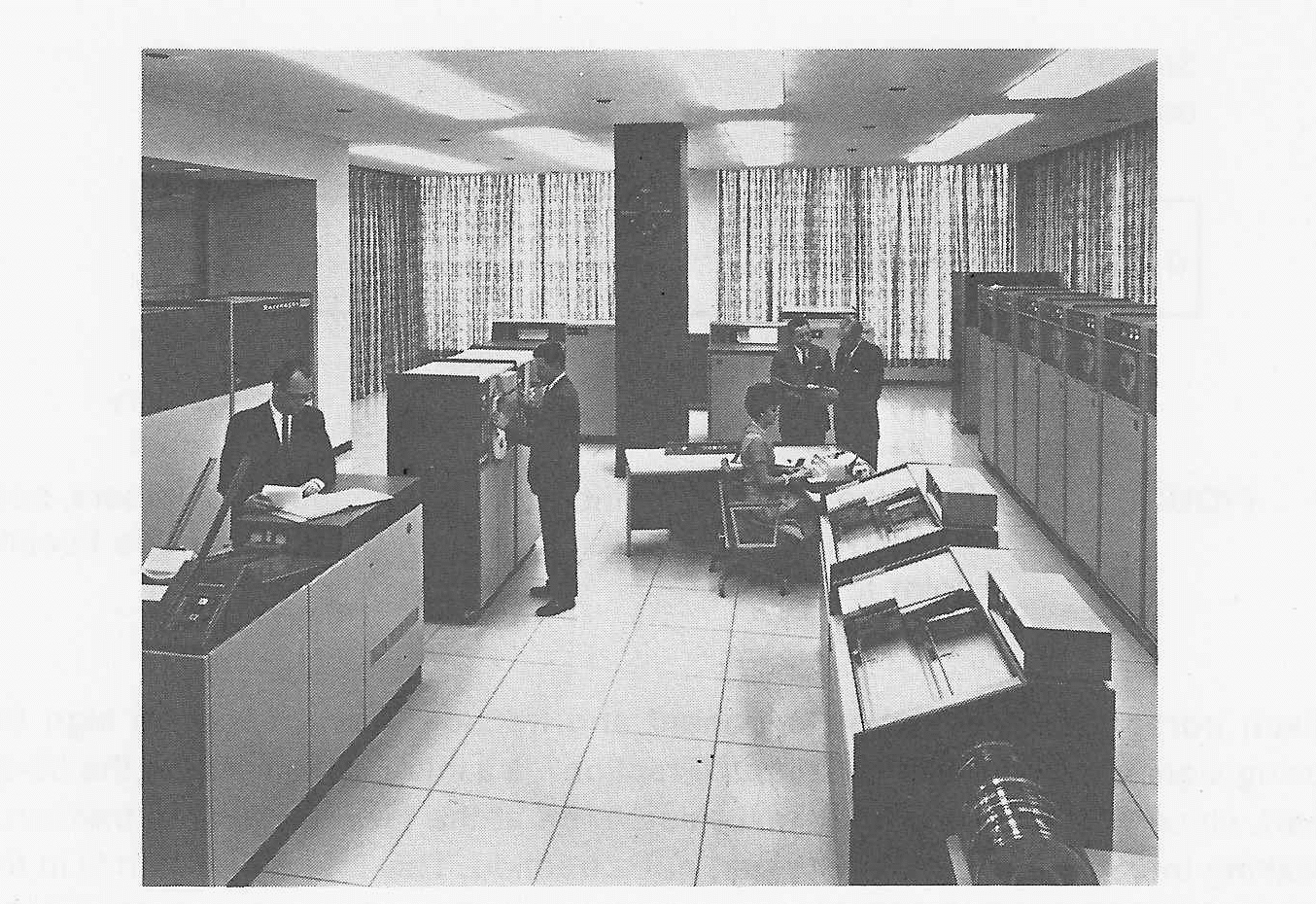 FIGURE 10.21 A Burroughs B5500 computer system. The B5500
was a very successful computer system based on a stack
architecture. (Photo courtesy of Burroughs Corporation.)
One point should be kept in mind during the discussion of the architecture of the B5500: there is virtually no assembly language programming for the B5500. In fact, there is no assembly language. This remarkable fact is a result of a conscious decision on the part of the designers of the Burroughs' computers. The designers saw the computer hardware as only a part of the overall computing system, composed of hardware and software. Thus, the B5500 was designed to efficiently execute higher-level languages, particularly Algol-like languages. Since it does this so well, there is no need for assembly language, and all code for Burroughs' computers is written in a higher-level language. This includes even the operating system, MCP.
With this in mind, we present a description of the Burroughs B5500.
The B5500 is a 48-bit machine with 15-bit addresses, allowing up to 32K words of memory. Each word can be either data or instructions. Data words can be interpreted in two ways. A 48-bit word can be interpreted as eight 6-bit characters; the character code is a variant of BCD.
 FIGURE 10.22 Representation of numbers on the
B5500. All numbers, both floating point and integer, are
represented in this floating point format.
Alternatively, the data word can be interpreted as a number. Numbers are represented in floating point notation, with a 6-bit exponent and a 39-bit fraction. Each portion of the number, exponent and fraction, has a separate sign bit, using sign and magnitude notation. "Fraction" is a misleading term for the 39-bit part, since the decimal point is assumed to be at the far right of the "fraction," making the 39-bit portion an integer, not a fraction. This integer portion is in the range 0 to 549,755,813,887. The exponent base is 8, so the range of representation is approximately 8-51 to 8+76 with about 12 places of accuracy. There is no integer number representation; integers are simply floating point numbers with a zero exponent.
The instruction set for the B5500 is composed of two separate sets: word mode instructions and character mode instructions. The computer operates in one of two modes; word mode or character mode, with separate instruction sets for both modes. One of the instructions in word mode switches the B5500 to character mode; one of the instructions in character mode switches to word mode. A one-bit flag register remembers the current mode. We consider word mode operation first.
In word mode, the B5500 is completely stack-oriented. Each instruction which needs an operand or generates a result uses the stack for the source of its operands and the destination of its results. For example, the ADD instruction takes the two words at the top of the stack, removes them from the stack, adds them, and places their sum back on the top of the stack. The stack is stored in memory and pointed at by a special register, the S register.
This approach to designing the instruction set has several advantages. No operand address need be specified in the instruction. A stack machine is thus called a 0-address machine. This makes the instruction very short, since it need only specify an opcode. Thus, programs are very short, saving memory. No registers are needed to act as accumulators or counters; all functions are performed on the top of the stack.
 FIGURE 10.23 Instruction format for word-mode
instructions. The two-bit type field selects either a literal
(00), operand (01), descriptor (11), or operation (10); this
determines the interpretation of the remaining 10 bits.
The B5500 has 12-bit instructions, allowing 4 instructions to be packed into each word. There are four types of instructions, selected by two bits of the instructions. These four types of instructions are,
The operand and descriptor instructions are more complex than the above description indicates. Notice for example that the descriptor function would appear to be the same as the literal function. Also both descriptor and operand instructions specify addresses, but only a 10-bit address, despite the fact that addresses are 15 bits. The reason for this is that the 10-bit "addresses" are not addresses into memory but rather indices into an area of memory called the Program Reference Table (PRT).
The PRT contains constants and simple variables for the program as well as pointers to more complex structures, such as subprograms and arrays. All references to subprograms and arrays are made indirectly through the PRT. The PRT acts like a symbol table (but without the symbols), allowing each symbol in a program to be represented by its index into the PRT rather than a complete 15-bit address. The descriptor function places the absolute 15-bit address of its PRT index on the stack.
The operations which can be performed on the B5500 are typical of most computers. The top two elements of the stack can be added, subtracted, multiplied, or divided, with the result placed on the top of the stack. These operations can be either single or double precision. All of these operations are floating point operations, but since integers are represented as unnormalized floating point numbers, these same operations can also be used on integers or mixed integer and floating point numbers. A special integer divide instruction allows an integer quotient and remainder to be generated from two numbers.
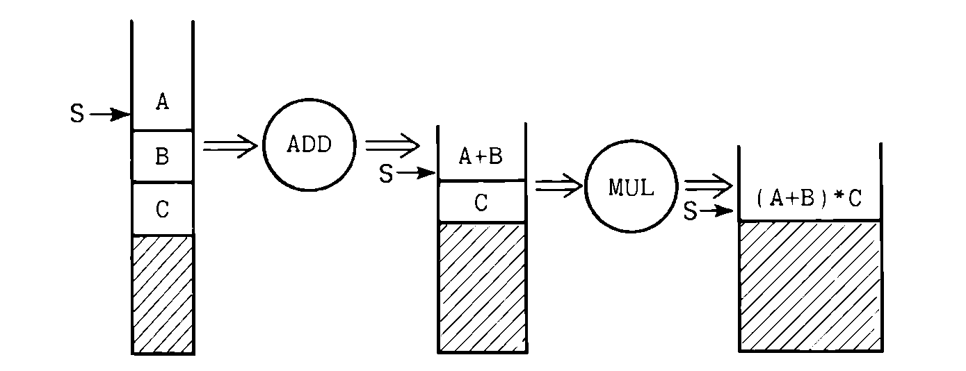 FIGURE 10.24 Stack operation on the B5500. All
operations are done on the top elements of the stack, with the result being
placed back on the stack. The S register points to the top of the stack.
Logical operations of AND, OR, equivalence (1 bit for each pair of identical bits, 0 bit for each pair of different bits), and negate operate on the top of the stack, placing the result on the top of the stack. Each word is treated as a string of 48 bits. These logical operations are useful in conjunction with the compare operators and for masking.
The compare operators compare the top two elements of the stack for equal, not equal, less, less or equal, greater, or greater or equal, whichever is selected, and places the result of the comparison (zero for false, nonzero for true) on the top of the stack. A special field compare instruction allows any two arbitrary fields of the top two elements of the stack to be compared.
Conditional jumps use the top of the stack to control jumping: jumping if true, not jumping if false. Unconditional jumps always jump. The address to which to jump is given on the top of the stack. Separate instructions exist for forward jumps and for backward jumps. The address on the stack is the offset (from the current instruction) of the instruction to which to jump. Since a jump will normally not be too far away, only the lower 12 bits of the stack address are used. This allows a jump to any instruction within 1023 words forward or backwards. In all cases the jump offset and logical value (for conditional jumps) are removed after the jump instruction is completed.
Storing operations require the value to be stored and the address of the location to be on the top of the stack. The value is stored in the memory location addressed, and normally both are removed from the stack. A special store operation allows the value to remain on the stack for further use, removing only the address from the stack.
A special set of instructions allows the top two elements on the stack to be interchanged, the top element to be duplicated, or the top element to be deleted.
To see how the stack structure of the B5500 affects its programming, consider the program to evaluate a simple arithmetic expression like,
((B+W) * Y) + 2 + ((M-L) * K)/ZFor the B5500, our program could look like
This expression was programmed in Chapter 4 with 10 MIX instructions, while the above B5500 program takes 15 instructions. However, remember that MIX instructions are 31 bits in length, while B5500 instructions are only 12 bits. Thus, the MIX program took 310 bits compared to the 180 bits for the B5500 program. Also the MIX program required a temporary storage location, while the B5500 program needs no temporary storage, storing all intermediate results on the stack.
One special control instruction for the B5500 changes the mode of execution to character mode. In character mode, the entire instruction is interpreted in a different manner. There is no stack. Two special registers point to two areas of memory called the source and the destination. Operations transfer from the source to the destination, compare the source to the destination, add or subtract the source to the destination (as decimal integers), and perform editing operations (like suppressing leading zeros). Two instructions are almost exactly like NUM and CHAR in MIX. The length of the character strings is included in each 12-bit instruction. Each instruction has a 6-bit repeat field and a 6-bit opcode field. This allows character strings to be any length from 0 to 63.
 FIGURE 10.25 Instruction format in character mode. Each
instruction has a 6-bit repeat count and a 6-bit opcode. All
operations are between two memory areas, the source character
string and the destination character string.
An interesting pair of special instructions is the BEGIN-LOOP/END-LOOP pair. When a BEGIN-LOOP opcode is encountered, a counter is initialized to the 6-bit repeat field in the instruction and the address of the BEGIN-LOOP instruction is remembered. When an END-LOOP instruction is executed, the counter is decremented. If it is still positive, the loop is repeated from the address following the BEGIN-LOOP instruction, if the counter is zero, the computer continues to the next instruction, following the END-LOOP instruction. These instructions allow loops on character strings without the need for an explicit counter, decrement, and conditional jump.
The input and output of information is handled by channels executing a channel program. The I/O start instruction starts the channel executing a channel program which starts at memory location 8. An interrupt system is used to signal completion of I/O and also to handle exceptional conditions such as overflow or underflow (of numbers or of the stack), divide by zero, memory parity errors, and so on. A 7-bit interrupt code is used to indicate the type of interrupt occurring. Interrupts are vectored through locations in low memory. Registers are stacked when the interrupt occurs, allowing the interrupted program to be restarted after the interrupt is serviced.
In discussing the CDC 6600, it is important to make clear at the start that the 6600 was not designed for the same purpose as the other computers described in this chapter. The 6600 was built for the express purpose of delivering the greatest possible computing power for the solution of large scientific computing problems. As such it has succeeded very well. The 6600 and the later 6400, 6500, 6700, and Cyber 70 models are not meant for the business data processing problems which typically involve much I/O and little computation. They were designed for problems which involve large amounts of floating point calculations.
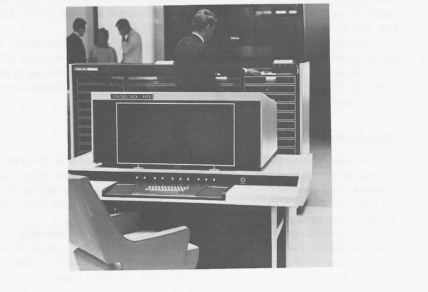 FIGURE 10.26 A CDC 6600. The 6600 is
composed of 11 separate computers: one central processor and
10 peripheral processors. One peripheral
processor is commonly used to drive the operator's console, shown in the
foreground. (Photo courtesy of Control Data Corporation.)
The design goals resulted in a dramatic change in the basic architecture of the computer. The CDC 6600 is not 1 processor but 11 separate processors: 1 main central processor (CP) and 10 peripheral processors (PP). Each of these processors has its own memory, registers, and instruction set. The objective is quite simple: to relieve the central processor of all input/output, bookkeeping, and control functions. The entire operating system of the 6600 resides in the peripheral processors. This is an extension to the extreme of the same ideas which lead to the design of the channels on the 360/370 computers. The idea is to relieve the CP of the responsibility for operating system functions, allowing it to devote itself totally to computation. The 6600 is an expensive computer system, costing from $3,000,000 to $5,000,000.
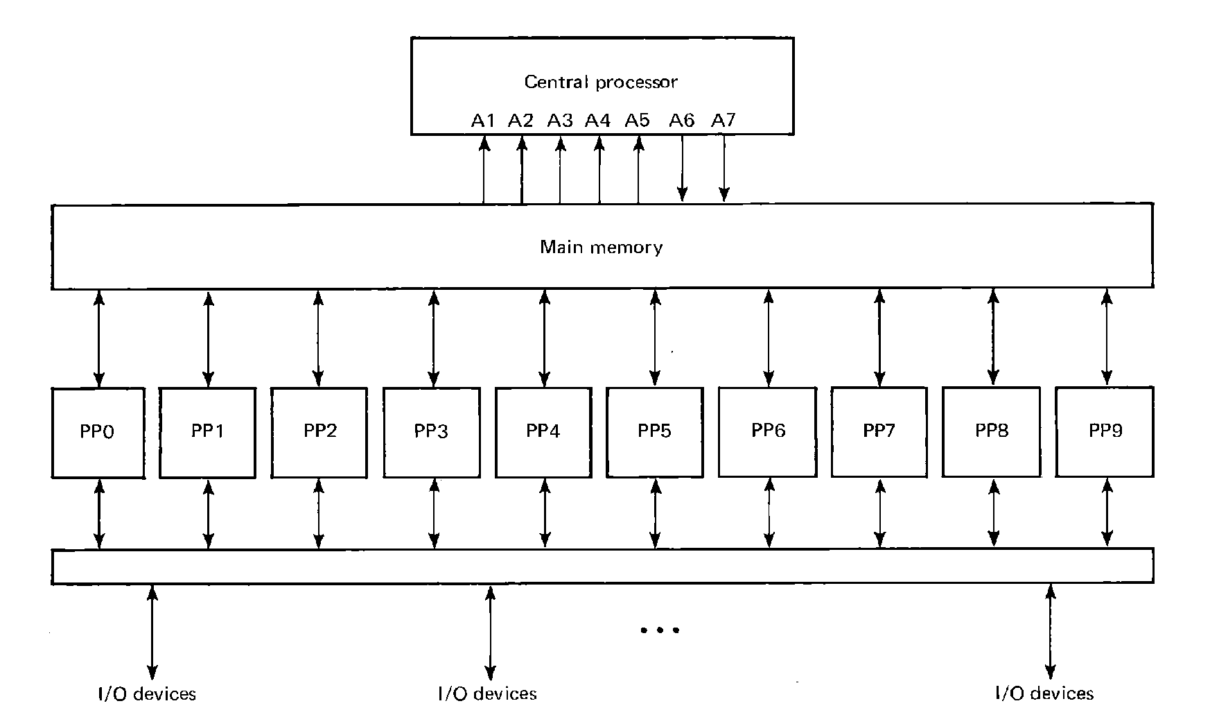 FIGURE 10.27 Block structure of the CDC 6600. I/O
devices are attached through a large switch to each of the
peripheral processors, which can pass information on to the
central processor through main memory.
Each of the peripheral processors is a 12-bit computer with its own 4K of memory and an 18-bit accumulator, the A register. Instructions are either 12-bits or 24-bits long and allow loading, storing, addition, subtraction, shifting, masking, and conditional jumps. A subroutine jump instruction stores the return address in memory and starts execution at the next instruction. Addressing modes allow 6-bit and 18-bit immediate operands, as well as direct and indirect addressing. All of these instructions access the PP's private 4K of memory. Additional instructions allow the PPs to copy words between central memory and its own memory.
The PPs have I/O instructions which allow each PP to do input or output on any I/O device, one word at a time. No interrupt system is used, so busy loop waiting, or polling, is needed for I/O. Remember, however, that when busy loop waiting is used, the entire computer system is not waiting, only the one PP doing that I/O. The other PPs can continue work.
The PPs are designed to perform I/O and operating system functions, not general computing. They normally execute only programs which are a part of the operating system. Thus, most programmers never have an opportunity to program the PPs. When the 6600 is discussed, most discussion centers on the central processor.
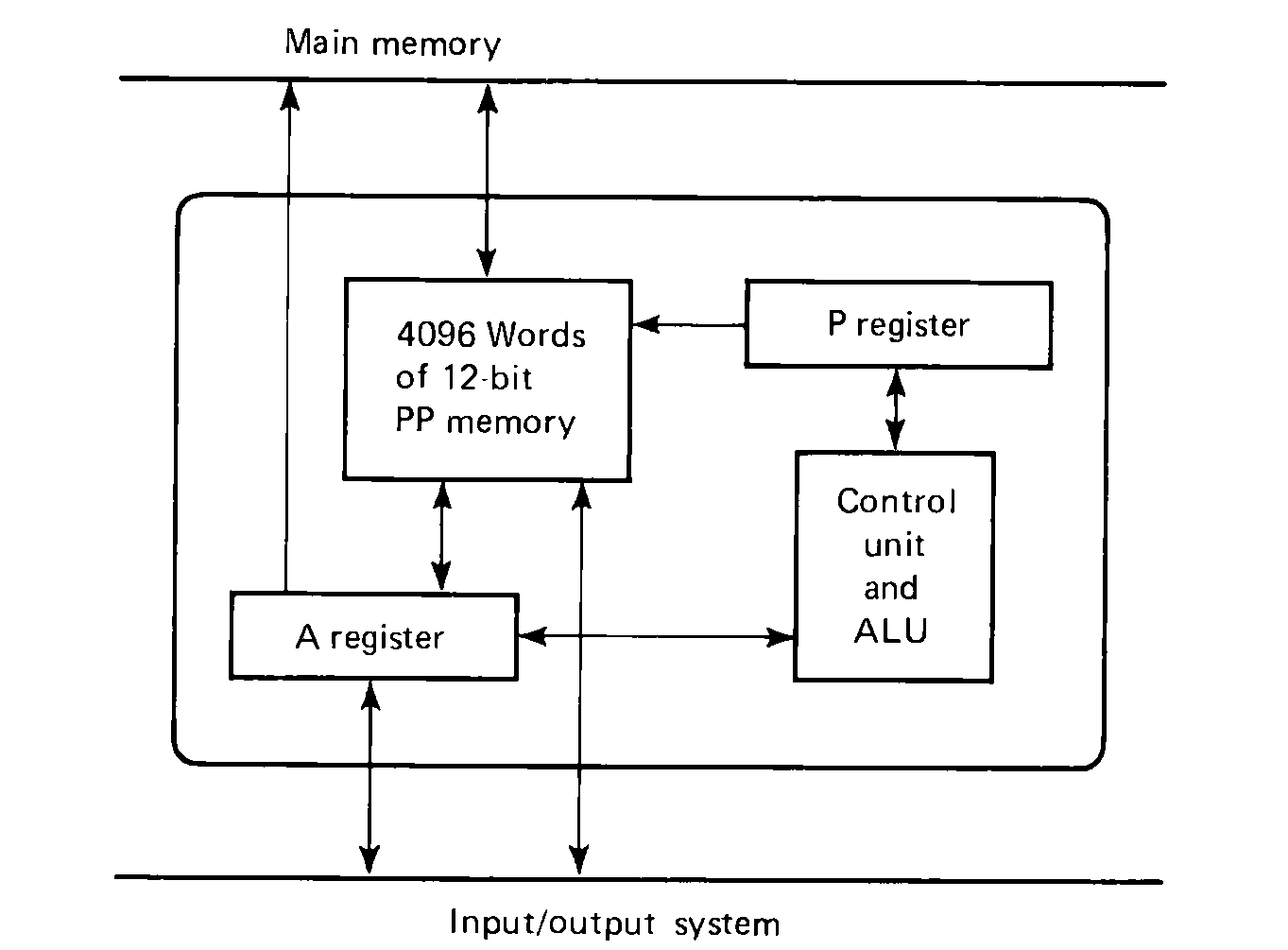 FIGURE 10.28 Block diagram of a peripheral processor
(PP). There are 10 PPs, and each has its own registers and 4096
12-bit words of memory.
The central processor was designed for scientific calculations. This implies floating point numbers and a desire for many digits of precision. This in turn implies a large word length. Correspondingly, the word length for central memory is 60 bits. Each 60-bit word can be copied to 5 12-bit PP words. Up to 256K words can be used on a 6600, since addresses are 18 bits.
A 60-bit word can represent integers, in a ones' complement notation, or 10 6-bit characters. The character code is of CDC's own design, called display code, but is only 6-bits per character, 64 characters. The characters provided are basically the same as those provided by the BCD character code.
A 60-bit word can also be interpreted as a floating point number in ones' complement notation, with an 11-bit, ones' complement base 2 exponent (but with a complemented sign bit) and a 48-bit fraction with a binary point to the right of the fraction. Special floating point numbers are used to represent "infinite" and "indefinite" numbers. Infinite numbers result from operations causing exponent overflow, while indefinite numbers result from using infinite numbers in operations.
The 6600 has 24 (plus or minus one) programmable registers:
The A registers are used to do all loading and storing of the X registers. Whenever an address is loaded into any of A1, A2, A3, A4, or A5, the contents of that memory location in memory is loaded into X1, X2, X3, X4, or X5, respectively. Whenever an address is put into A6 or A7, the contents of X6 or X7, respectively, is stored into the memory word at that address. Memory is only loaded from or stored into as a result of setting one of the appropriate A registers (A1 though A5 for loading; A6 or A7 for storing) to an address.
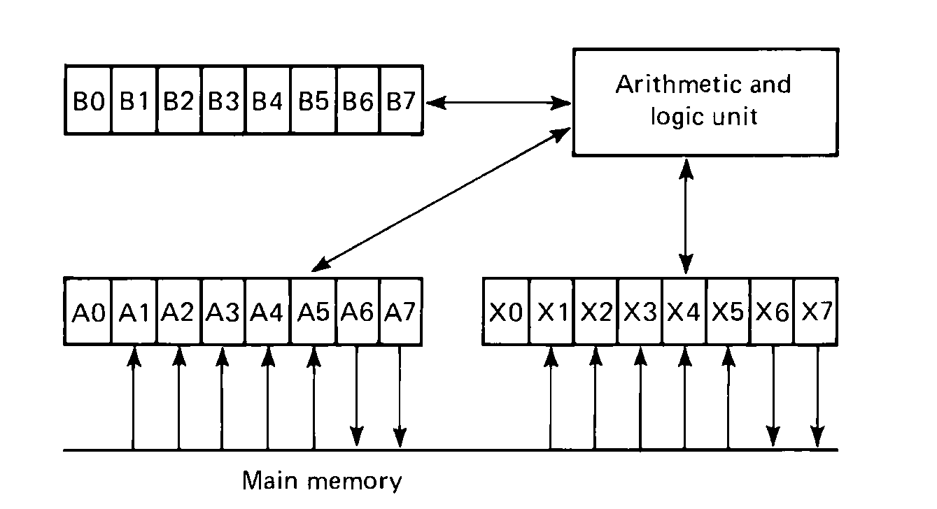 FIGURE 10.29 The central processor of a CDC 6600. The A
and B registers are 18-bit registers for holding counters and
addresses; the X registers are 60-bit registers for holding
integer, character, and floating point operands.
A few of the registers are special. A0 and X0 are not connected nor do they cause loading or storing. A0 is essentially an extra index register, while X0 is a "free" operand register. B0 is always zero. It is possible to "store" into B0 any value, but it will always be read out as zero. This is actually very useful, and many programmers go one step farther, initializing B1 to 1 and leaving it as 1 for the duration of their programs.
The 6600 has two types of instructions. The short form is 15 bits with an opcode field (6 bits), and three 3-bit register fields (i, j, and k). The register fields select one of the eight registers for the instruction. The opcode determines whether the A, X, or B registers should be used. The long form of instruction has the same format, except the k field is an 18-bit ones' complement number, denoted as K. The K field most often holds an 18-bit address.
 FIGURE 10.30 Instruction formats for the CDC 6600. Several
instructions are packed into each word. The opcode defines the
length of the instruction. K is an 18-bit constant; the
other fields (i, j, k) select one of eight registers.
Having instructions of varying lengths is not unusual, but notice that both instruction lengths are smaller than the size of the basic addressable memory unit (in this case a 60-bit word), not larger, as in the PDP-11 and IBM 370. Multiple instructions are packed into each word. In the best case, four 15-bit instructions can be packed into one 60-bit word. Alternatively, two 30-bit instructions, or two 15-bit and one 30-bit instruction can be packed into one word. If, in writing a program, you encounter the situation of having three 15-bit instructions (or one 15-bit and one 30-bit instruction) in a word, and the next instruction is 30 bits, then the last 15 bits of the word are padded with a no-operation (NOP), and the next word gets the 30-bit instruction in its upper 30 bits. If an instruction is to be jumped to, it must be the first instruction in a new word. This can result in a word being padded with up to three NOPs.
The instruction set itself is quite simple. With only 6 bits for the opcode field, only 64 opcodes are possible. The instructions can be split into three groups: the set instructions, the jump instructions, and the computational instructions.
The set instructions are used to put values into the A, B, and X registers. The values are 18-bit quantities which result from addition or subtraction of the contents of A, B, and X registers, or (in the long format instructions) the number K. Any Ai, Bi, or Xi register can be set to
The contents of registers can be tested and a jump made on the result by the jump instructions. The jumps allow X registers to be tested for positive, negative, zero, nonzero, indefinite, or infinite values. If the condition is true for the selected X register, a jump is made to the address K given in the instruction. In addition, jumps can be made as the result of comparing any two B registers for equality, nonequality, greater than or equal, or less than. Since one of these registers can be B0, this allows jumps if a B register is positive, negative, zero, nonzero, nonnegative, or nonpositive. Two other jumps are an unconditional jump and a subroutine jump. A subroutine jump to location K from location P will result in a jump instruction to location P+1 being stored in location K, and execution continuing at K+1. A return to the calling program is effected by jumping to K (which jumps back to P+1).
The remaining instructions are the computational ones. These are the instructions which actually compute. They include Boolean operations (AND, OR, and exclusive-OR of X registers and their complements), shifts (left or right, end-off or circular), addition, subtraction, multiplication (both integer and floating point), and division (floating point). Additional instructions help to multiply and divide double precision numbers and to convert between integers and floating point numbers.
The contents of X registers can be copied from register to register by ANDing or ORing the source register with itself. This is probably the most common use of the Boolean instructions: to move values between registers.
A few miscellaneous instructions allow the CP to do nothing (NOP) or stop (PS).
And that is all the instructions for the 6600 (give or take a few). There are no load or store instructions (this is done by setting A registers), no character handling instructions (done by shifting and masking with the Boolean operations), and no I/O instructions (done by the PP's). The instruction set is very simple, possessing a kind of elegance for its simplicity. This makes the computer relatively easy to program (once you get used to it).
However, it should be admitted that although it is possible to program the 6600 in a very straightforward manner, this is seldom done. The main reason for this is that very large increases in speed can be obtained by careful use of registers, selection of operations, and ordering of instructions. Only the very sophisticated programmer can consider all of these factors and produce truly optimal code.
Since there are two computers with two separate instruction sets for the CDC 6600 (CP and PP), two assemblers would be expected. However, since most of the code in an assembler is independent of the instruction set, only one assembler is used. A pseudo-instruction selects the PP opcode table for PP programs; normally the opcode table for the CP is used. This assembler runs on the CP, but not on the PPs. Thus, the PPs have no assembler for PP assembly language which runs on a PP. The CP assembler for PP assembly language is a cross-assembler, an assembler which runs on one computer and produces code to be executed on another computer.
The statement format for the 6600 assembly language is the same as for many other computers: free-format, composed of four fields: label, opcode, operand, and comment. The label field must start in column 1 or 2, if there is a label. (Labels are allowed to start in column 2 because the operating system uses the Fortran convention of using column 1 for carriage control information when a file is printed. Thus, if labels started in column 1, and the program were simply copied onto the printer, the first letter of each label would be interpreted as a carriage control character.)
The central processor assembler recognizes the special symbols A0, A1, …, A7, B0, B1, …, B7 and X0, X1, …, X7 as the names of the corresponding registers. The opcode field plus the form of the operand field are used to determine the opcode and assembled instruction. For example, all set instructions use the mnemonic "S" followed immediately by the register to be set. The type of set and the other registers involved are indicated by the form of the operand. The following examples might illustrate this
A large number of pseudo-instructions are used. Each program is preceded by an IDENT pseudo-instruction (which identifies and names the program), and terminates with an END pseudo-instruction. DATA or CON pseudo-instructions can be used to define constants; DIS defines strings of characters (like ALF), and BSS reserves memory locations. ORG is used to set the location counter, but almost all programs are relocatable, so it is seldom used. ENTRY and EXT pseudo-instructions declare entry points and externals. The EQU defines a symbol for the symbol table. Conditional assembly and macro instructions are also available.
Some of the more unusual pseudo-operations include BASE, which can be used to define the base in which numeric constants are interpreted (octal or decimal); PPU which declares the program which follows to be a PP program and not a CP program; and OPDEF, which allows the programmer to define his own entries for the opcode table. The assembler is two-pass.
Programming the 6600 is somewhat different from programming other computers. All operations are done on registers and loading and storing operations are done in a somewhat unconventional manner. Most of these problems disappear as experience and familiarity with the machine are gained. The more important problems deal with the coordination of the CP and the ten PPs to allow a program to perform both computation and I/O as necessary. Since the CP can do no I/O, it must request the PPs to do all I/O for it. This leads to some interesting problems in operating system design, but is beyond the scope of this book.
As with most computers, the reference manuals published by the manufacturer provide the most authoritative description of the hardware and assembler for the computer. For the 6600, these are the "Control Data 6000 Series Computer Systems Reference Manual," and the "Compass Reference Manual". Another source is the excellent book by one of the designers of the 6000 series of computers, Thornton (1970), which describes the 6600 and its hardware design. Programming techniques for the central processor are described in the text by Grishman (1974).
One of the major concerns which must be considered in designing a computer is the available technology. Charles Babbage was unable to complete his Analytical Engine in the nineteenth century not because of faulty design, but simply because his design exceeded by almost a century the technology to implement his ideas. Within the last five years, however, the technology of electronic circuits has improved to the point that an entirely new type of computer is possible: the microcomputer.
The transistor started the semiconductor revolution, allowing computers to replace the bulky vacuum tubes with the smaller, faster, and more reliable solid state devices. Originally these devices (transistors, resistors, capacitors, diodes) were used as discrete components, but soon they were combined into combinations of devices produced as an entity. This is known as small-scale integration (SSI). SSI allowed several gates to be put on a single silicon chip. Medium-scale integration (MSI) increased the number of components that could be placed on a single chip, so that an entire register might be one chip. Most recently, large-scale integration (LSI) has allowed thousands of components to be put on a single chip. In particular, LSI makes possible the construction of an entire CPU on one chip. This includes the ALU, registers, and control logic. Separate chips can be used to provide memory and I/O driver circuits.
One of the first computers-on-a-chip, or microprocessors, to be developed was the Intel 8008. This was used to control an "intelligent" CRT terminal. The 8008 was replaced by the Intel 8080. The 8080 has more instructions than the 8008 and is faster, but is also upwards compatible, so any 8008 program will also run on the 8080. The 8080 has been upgraded to the 8080A and recently the 8085 has been announced. The 8085 is compatible with the 8080, but runs 50 percent faster.
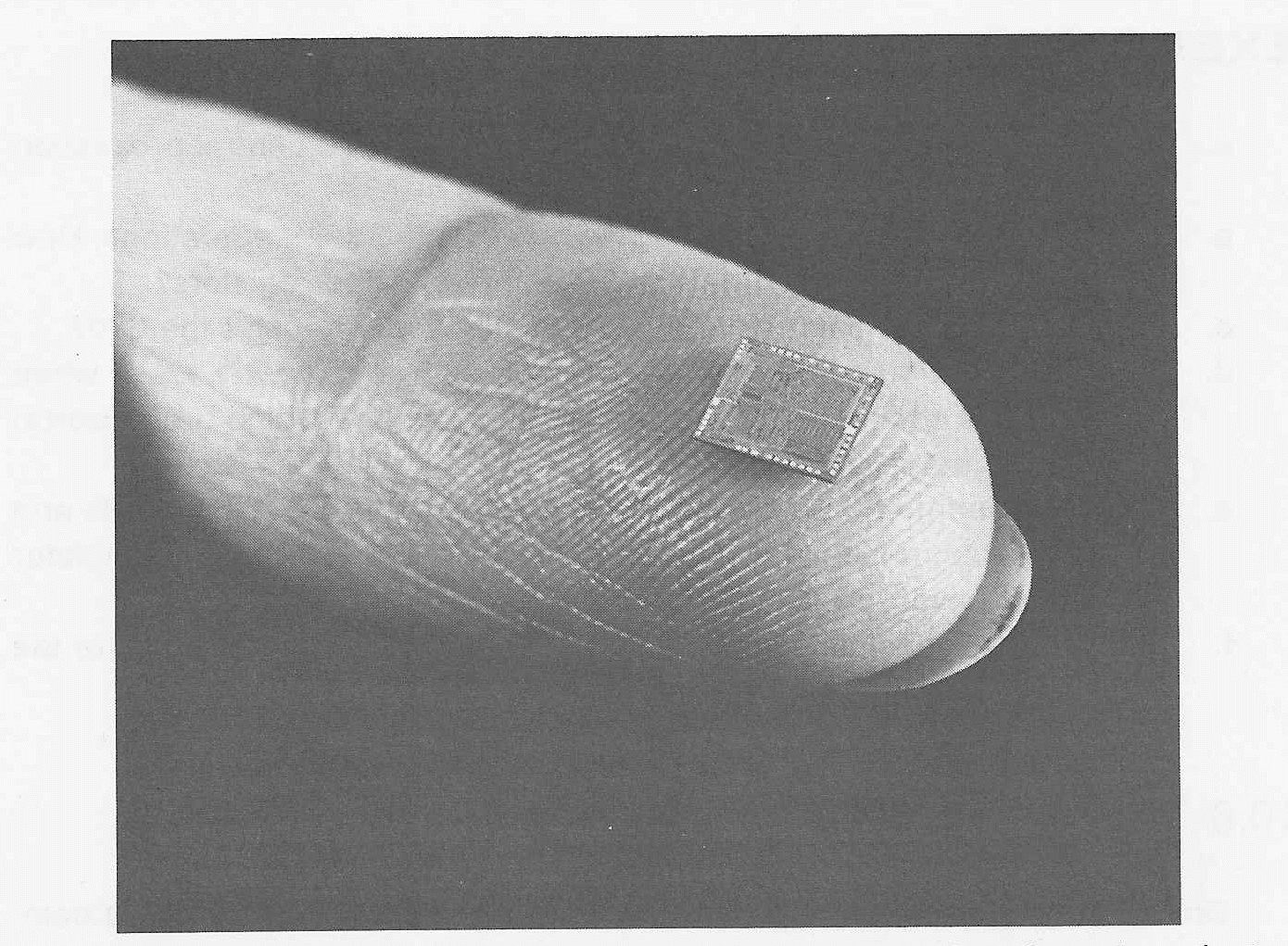 FIGURE 10.31 The Intel 8080 CPU. This small chip of
semiconductor material includes all of the logic for the
arithmetic and logic unit and control unit for the 8080. The
entire chip is less than 1/2 inch on each side. (Photo courtesy
of Intel Corporation.)
The 8080 is certainly not the only microprocessor. The Motorola M6800 is another popular 8-bit microprocessor, while the Intersil IM6100 is a 12-bit PDP-8 compatible processor, and the LSI-11 microprocessor is a 16-bit PDP-11 compatible processor. Zilog Corporation makes the Z80 which is 8080-compatible but twice as fast and uses less power. RCA manufactures the COSMAC micro-processor; Data General manufactures the microNOVA microprocessor; and so on. We have chosen to describe the 8080, not because it is best, but only because it is well-known, widespread, and similar to many other microprocessors.
The 8080 is an 8-bit machine, so memory is made up of 8-bit bytes. Each byte has a separate address (byte-addressable). If 8-bit bytes were used as addresses, only 256 bytes would be addressable, so 16-bit addresses are used. This allows up to 65,536 bytes of memory to be used.
The 8080 chip does not have memory on it; memory is available on other chips, such as the 8102 chip with 1024 bits of memory. Typically, an 8080 will have from 4K to 16K bytes of memory. For dedicated applications, programs could be in read only memory (ROM) with only a small amount of read-write random access memory (RAM) for storing data and variables.
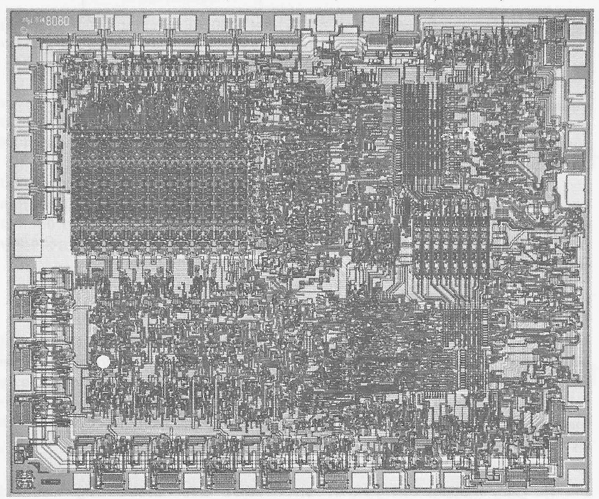 FIGURE 10.32 An Intel 8080 CPU chip.
This photomicrograph shows the structure of a single chip which includes
registers (upper left), an arithmetic and logic unit (lower half), and
control circuits. (Photo courtesy of Intel Corporation.)
The 8080 has several registers. A 16-bit program counter contains the address of the next instruction, and a 16-bit stack pointer contains the address of the top of a stack in memory. The stack is used for subroutine return addresses and can also be used for temporary storage and parameters.
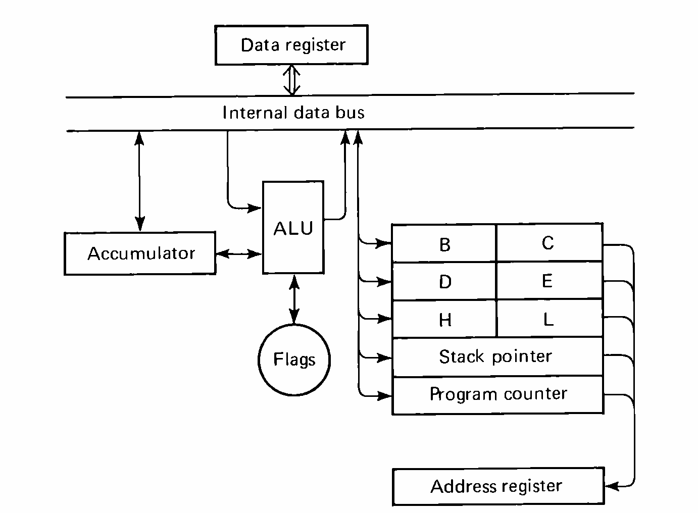 FIGURE 10.33 Block diagram of the Intel 8080. All
communication between the CPU and memory or external devices is
via the 8-bit data register and the 16-bit address register.
The 8-bit accumulator (A) is used for arithmetic functions. In addition there are six 8-bit general registers: B, C, D, E, H, and L. These registers can be used to store 8-bit bytes or used as register pairs (B,C), (D,E), and (H,L) to hold 16-bit quantities, generally addresses. A set of five 1-bit flag registers are used as condition code indicators to signal when the result of an arithmetic operation is zero, negative, generates a carry, has even parity, or generates a carry out of bit 3 (for decimal arithmetic).
Data is stored as 8-bit binary integers and can easily be interpreted as signed two's complement or unsigned 8-bit integers. Double precision (16-bit) integers can be used by multiple-precision programming techniques and even floating point numbers could be simulated with proper programming, but generally programs work with signed or unsigned 8-bit or 16-bit integers.
The 8080 instruction set uses an 8-bit opcode. This allows up to 256 different instructions, of which 12 are not used by the 8080. Many of these opcodes operate on the registers and so do not have operands. A few use the byte following the opcode for an 8-bit "immediate" constant, or the two bytes following the opcode for an address. Thus, an instruction may be one, two, or three bytes in length, depending upon the opcode.
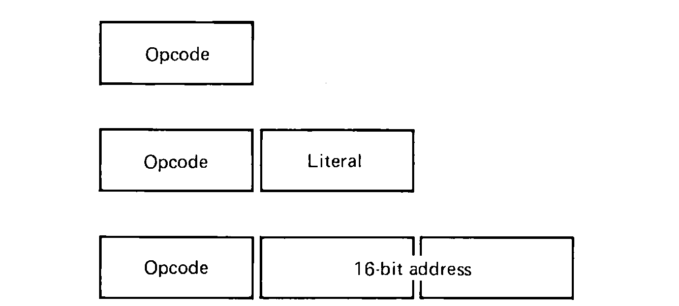 FIGURE 10.34 Instruction formats
for the Intel 8080. Instructions can be one, two, or three bytes long,
depending upon the opcode.
The instructions can be divided into four types:
Notice that the above commands may reference memory. Memory can be addressed in several ways. First, it can be addressed directly. In this case the two bytes following the opcode specify the address of the memory location. Second, memory can be addressed indirectly through the register pairs (H,L), (B,C), or (D,E). Most commonly (H,L) is used as an address of a memory location.
Memory can also be accessed via the stack pointer and data may be in the instruction for immediate use. Immediate operands can be 8 or 16 bits, depending on the opcode. Thus, addressing modes include immediate, direct, and indirect (through a register). Not all addressing modes are possible with all instructions.
The data transfer instructions include instructions to move data between any two registers, or between a register and memory. This allows both loads, stores, and the entering of immediate data.
Arithmetic instructions allow the contents of any register or memory location to be added or subtracted from the accumulator. Memory is addressed only indirectly through the (H,L) register pair, so to add the contents of an arbitrary memory location, x, to the accumulator would require first entering the address of x into (H,L) and then adding. Immediate adds and subtracts (increments and decrements) are also possible.
Remember that the accumulator is an 8-bit register, so all arithmetic is 8-bit arithmetic. To allow multiple-precision arithmetic to be programmed easily, the carry bit records the carry (for addition) or the borrow (for subtraction) out of the high-order bit. Instructions allow this carry to be added to the accumulator. Thus, to add two unsigned 16-bit integers, a program would first add the low-order 8-bit bytes of each operand, store the sum back in memory, and then add the two high-order 8-bit bytes and the carry from the low-order addition. If there was a carry from this addition, overflow has occurred.
The logical operators of AND, OR, and XOR are available also. These instructions operate between the accumulator and any register, memory [indirect through the (H,L) register pair], or immediate operand. Rotate instructions allow the contents of the accumulator to be rotated (circular shift) left or right one bit position, with or without the carry bit. The accumulator can also be complemented.
Another set of instructions allow any register or memory location [addressed indirect through the (H,L) register pair] to be incremented (by one) or decremented (by one). This is particularly useful for counters and index addresses.
Finally, the accumulator can be compared with any other register or memory location [addressed indirectly through the (H,L) register pair], or an immediate operand. The results of this comparison are used to set the condition flags.
The jump instructions allow the program to jump, either conditionally or unconditionally, to any memory location. The jump address is contained in the two bytes following the jump opcode. Conditional jumps are based on the value of the condition flags, which may be set on the basis of a compare, addition, subtraction, or logical operation.
Subroutine linkage is performed by two special instructions, CALL and RET. These allow a subroutine to be called and later return. The return address of the call is automatically pushed by the CALL instruction onto the stack pointed to by the stack pointer register. The RET instruction then pops the top two bytes off the stack and jumps to that address to return from the subroutine call. This mechanism makes it easy to write recursive subroutines. The designers of the 8080 then went one step farther and allowed subroutine calls and returns to be conditional as well as unconditional. A subroutine call or return can be conditional on the value of the condition flags in the same way as the conditional jumps.
In addition to being used by CALL and RET, the stack can be used directly. Specific instructions allow register pairs to be pushed onto or popped from the stack. The accumulator and condition flags can also be saved and restored using the stack. This allows convenient saving and restoring of registers in subroutines or interrupt handlers.
Instructions for halting the CPU and doing nothing (NOP) are also provided.
Four instructions control input and output. An IN instruction moves one 8-bit byte from an I/O device to the accumulator, while an OUT instruction moves one 8-bit byte from the accumulator to an I/O device. The device number is specified in the byte following the opcode, allowing up to 256 I/O devices. These instructions are similar to the MIX I/O commands, but there is one major difference: the MIX system provides the JBUS and JRED instructions to determine when the I/O devices are busy or ready; the 8080 has no such instructions.
There are several ways to solve this problem. One would be to assign two device numbers to each I/O device. The even device number would be used for control and status information and the odd device number for data. This effectively reduces the number of different I/O devices to 128, still a reasonably large number, and the additional control circuitry is not great.
Another approach that has been suggested is to assign I/O devices to memory addresses. Thus, when an address is sent from the CPU, ostensibly to memory, special circuitry separates the addresses into some which are sent on to the memory modules and others that are sent to I/O devices. For example, using the high-order bit to choose between memory addresses and I/O devices would allow up to 32,768 bytes of memory and 32,768 different I/O devices. This scheme is similar to the approach of the PDP-11.
There are two other I/O techniques which can be used with the 8080. For high-speed devices, DMA transfers can be made directly to memory. To avoid interference at the memory between the I/O device doing the DMA transfer and the CPU, it may be necessary to suspend all CPU operations during the transfer. This will be necessary only if the memory cycle time is too long to allow the memory units to service both the CPU and the DMA I/O device.
Finally, the 8080 has an interrupt structure. Two instructions allow the interrupt system to be turned on and off. When the interrupt system is on, and a request for an interrupt is made by an I/O device, the interrupt system is turned off and an interrupt phase is entered. The interrupting I/O device is requested to provide one 8-bit opcode to the 8080 processor. After this instruction is executed, the 8080 continues its normal instruction execution cycle.
The instruction supplied by an interrupting I/O device can be any 8080 instruction, but, of course, what is desired is a jump to an interrupt routine in such a way that control can be resumed at the interrupted instruction; that is, a subroutine jump to an interrupt routine. The problem is that all jumps and subroutine calls require an address, meaning that subroutine call instructions are three bytes in length. To remedy this problem, a special instruction has been included in the instruction set. This instruction, called a restart, has a 3-bit field in the 8-bit opcode which specifies one of the 8 addresses, 0, 8, 16, 24, …, 56. The restart instruction cause a subroutine call to the address specified by its 3-bit field. This pushes onto the stack the address of the interrupted instruction.
Typically then an interrupt instruction is a restart to one of the 8 restart addresses. At each of these addresses is a short program segment which saves registers and then jumps to another section of code to service the interrupt. After the interrupt has been serviced, the interrupt system is turned back on, and processing is returned to the interrupted instruction. By storing interrupt return addresses and registers on the stack, it is possible to allow interrupts to occur during interrupt handling subroutines.
Several assembly languages for the 8080 exist and more are being developed. One sizable market for the 8080, and other microprocessors, is the computer hobbyist. Since a complete 8080-based computer costs less than $500, many people are buying them for personal experimentation and use. Since assemblers are relatively straightforward to write (as shown in Chapter 8), many people are writing their own. We describe here the assembly language provided by Intel.
Each assembly language statement has four fields, as usual: the label field, the opcode field, the operand field, and the comment field. Input is free-format. The general form of an assembly language statement is:
The operand field may or may not be needed, depending upon the opcode. It can contain a constant, a symbol, or an expression. Constants can be specified as decimal, octal, hexadecimal, binary, or an ASCII character. Symbols are one to five characters (the first character being alphabetic) and must appear as labels somewhere. The special symbol $ is the value of the current location counter. Expressions are constructed from constants and symbols and the operators of +, -, *, /, MOD (modulo), NOT, AND, OR, XOR, SHR (shift right), and SHL (shift left). Parentheses can be used to force the order of evaluation; otherwise evaluation is by precedence of operators, similar to most higher level languages.
Pseudo-instructions include
| DB | Define a byte of data | |
| DW | Define a word of data | |
| DS | Reserve storage (like a BSS) | |
| ORG | Define the location counter value | |
| EQU | Define a symbol value | |
| SET | Like EQU but the symbol can be redefined later | |
| END | End of assembly |
Conditional assembly is provided by IF and ENDIF pseudo-instructions. The expression in the operand field is evaluated, and if it is zero, the statements between the IF and the ENDIF are ignored. If the expression value is nonzero, the statements are assembled.
Macros are available by using the MACRO and ENDM pseudo-instructions for macro definition. The MACRO pseudo-instruction specifies the macro name (in the label field) and a (possibly empty) list of parameter names in the operand field. For an instruction set as primitive as the 8080, macros are very important for convenient programming.
Most of the programming techniques for the 8080 are very similar to those of the PDP-8, although the instruction set is actually more powerful for the 8080. Complex instructions like multiplications and division are programmed either as macros or subroutines, as space and time demand. Array processing is easiest by keeping the base address in a register pair and incrementing or decrementing to move through the entire array. Subroutine calls use the stack for return addresses. Parameters can be passed in the registers, on the stack or in memory. The use of subroutines and macros is very important in the production of good assembly language programs.
By this point, we hope you are aware of both the basic similarities among computer systems and the points of difference. Each new computer should be considered for the following design points.
What is the basic unit of memory (word, byte) and its size (8 to 128 bits)? What are the variations on this basic unit (bytes, halfwords, fullwords, double-words)? How big can memory be and what is the address size (8 to 32 bits)? What forms of data are represented (integers, floating point, decimal, character strings) and in what representation (ones' complement, two's complement, packed, zoned, etc.)?
What registers are available for use by the programmer, their size and usage (accumulators, index registers, floating point registers, general purpose registers, condition codes)?
What is the instruction set and its format? What addressing modes are available (direct, indirect, indexed, auto-increment or decrement)? Are the instructions three-address (A = B op C), two-address (A = A op B), one-address (register = register op A), or zero-address (all operations use the top elements of a stack and replace their results on the stack)? How is loading, storing, testing, and arithmetic handled? What jump conditions are available and how is a subroutine jump done? How many (bits, bytes, words) does each instruction format take?
What is the assembly language statement format? What is the maximum symbol length and any other restrictions on the naming of symbols? How are fields of the statement defined? What are the mnemonic opcodes and the pseudo-instructions? What forms of expressions are allowed? What is the symbol for the location counter?
How is I/O performed (CPU, DMA, channels)? What are the I/O instructions? Is there an interrupt structure and what kind (vectored, priority)? What happens when there is an interrupt? Are some device numbers interpreted in a special way, and if so, what way?
These are the questions which need to be asked about a new computer. With a familiarity with the computers considered in this book, you should be able to both ask these questions and to understand their answers. Within a short period of time, you can then be programming in assembly language on any new computer that you find.
| MIX | PDP-8 | HP2100 | PDP-11 | IBM 370 | CDC 6600 | |
| Word Size (in bits) | ||||||
| Addressable Memory Unit | ||||||
| Integer Number Representation | ||||||
| Major Registers | ||||||
| Bits in Address | ||||||
| Opcode Size (in bits) |