| Home | Up | Questions? |
In this chapter, we give formal definitions for the basic Petri net concepts. These basic concepts are used throughout our study of Petri nets and so are fundamental to a correct understanding of Petri nets.
Our formalisms are based on bag theory, an extension of set theory. If you are not familiar with bag theory, we suggest you read the appendix for the relevant concepts.
The definitions given here are similar in type to
definitions in automata theory [Hopcroft and Ullman 1969].
In fact, they define a new class of machines, the Petri net
automaton. As we shall see later (Chapters 5, 6, 7, and 8),
this point of view can lead to some interesting results in
formal language theory and automata theory.
2.1. Petri Net Structure
A Petri net is composed of four parts: a set of places P, a set of transitions T, an input function I, and an output function O. The input and output functions relate transitions and places. The input function I is a mapping from a transition tj to a collection of places I ( tj ), known as the input places of the transition. The output function O maps a transition tj to a collection of places O ( tj ) known as the output places of the transition.
The structure of a Petri net is defined by its places, transitions, input function, and output function.
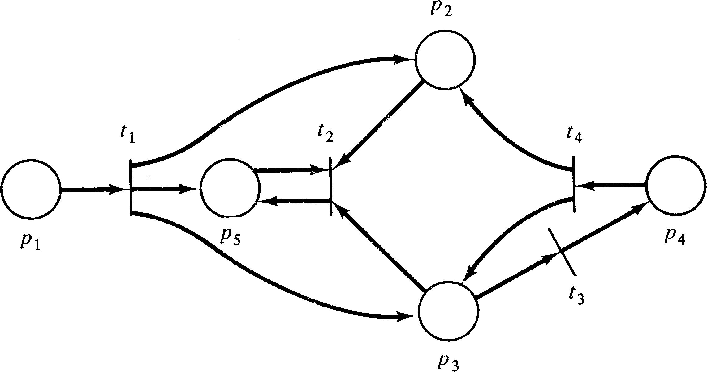
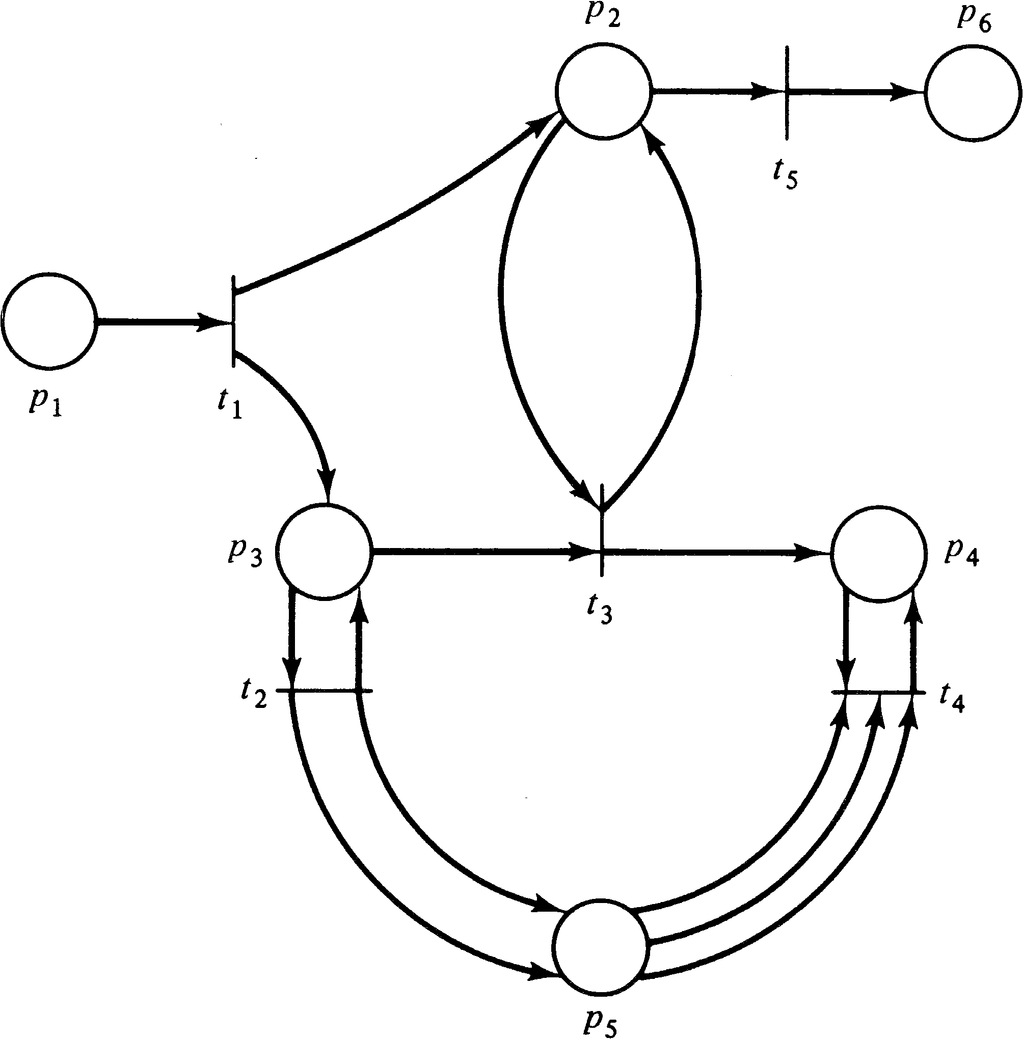
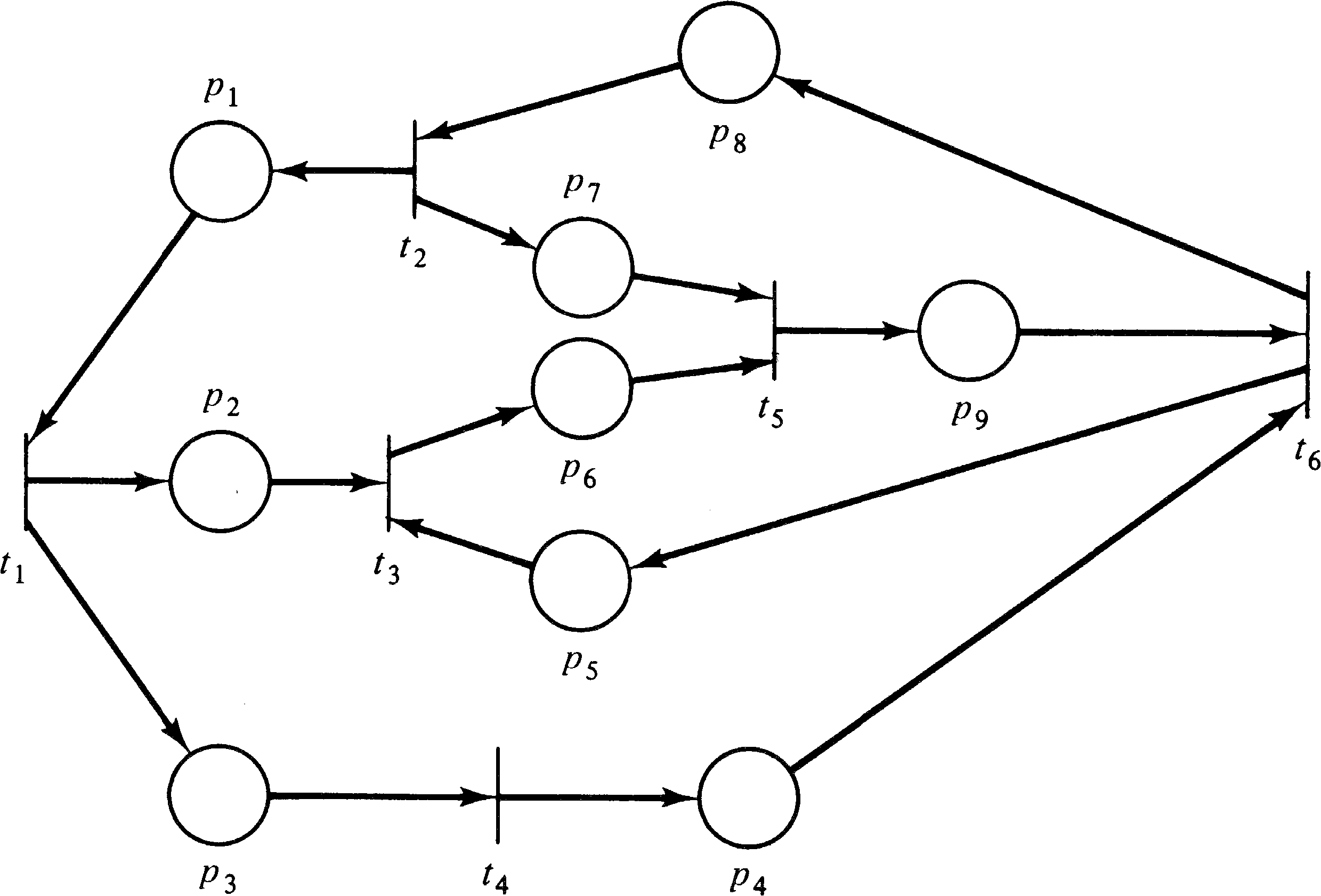
Examples of Petri net structures are given in Figures 2.1,
2.2, and 2.3.
| C | = | (P, T, I, O) | |||||
| P | = | { p1, p2, p3, p4, p5 } | |||||
| T | = | { t1, t2, t3, t4 } | |||||
| I(t1) | = | { p1 } | O(t1) | = | { p2, p3, p5 } | ||
| I(t2) | = | { p2, p3, p5 } | O(t2) | = | { p5 } | ||
| I(t3) | = | { p3 } | O(t3) | = | { p4 } | ||
| I(t4) | = | { p4 } | O(t4) | = | { p2, p3 } | ||
| C | = | (P, T, I, O) | |||||
| P | = | { p1, p2, p3, p4, p5, p6 } | |||||
| T | = | { t1, t2, t3, t4, t5 } | |||||
| I(t1) | = | { p1 } | O(t1) | = | { p2, p3 } | ||
| I(t2) | = | { p3 } | O(t2) | = | { p3, p5, p5 } | ||
| I(t3) | = | { p2, p3 } | O(t3) | = | { p2, p4 } | ||
| I(t4) | = | { p4, p5, p5, p5 } | O(t4) | = | { p4 } | ||
| I(t5) | = | { p2 } | O(t5) | = | { p6 } | ||
| C | = | (P, T, I, O) | |||||
| P | = | { p1, p2, p3, p4, p5, p6, p7, p8, p9 } | |||||
| T | = | { t1, t2, t3, t4, t5, t6 } | |||||
| I(t1) | = | { p1 } | O(t1) | = | { p2, p3 } | ||
| I(t2) | = | { p8 } | O(t2) | = | { p1, p7 } | ||
| [(t3) | = | { p2, p5 } | O(t3) | = | { p6 } | ||
| I(t4) | = | { p3 } | O(t4) | = | { p4 } | ||
| I(t5) | = | { p6, p7 } | O(t5) | = | { p9 } | ||
| I(t6) | = | { p4, p9 } | O(t6) | = | { p5, p8 } | ||
A place pi is an input place of a transition tj if pi ∈ I ( tj ) ; pi is an output place if pi ∈ O ( tj ) . The inputs and outputs of a transition are bags of places. A bag is a generalization of sets which allows multiple occurrences of an element in a bag. The appendix contains a description of bag theory. The use of bags, rather than sets, for the inputs and outputs of a transition allows a place to be a multiple input or a multiple output of a transition. The multiplicity of an input place pi for a transition tj is the number of occurrences of the place in the input bag of the transition, # ( pi, I ( tj )) . Similarly, the multiplicity of an output place pi for a transition tj is the number of occurrences of the place in the output bag of the transition # ( pi, O ( tj )) . If the input and output functions are sets (rather than bags), then the multiplicity of each place is either zero or one.
The input and output functions can be usefully extended to map places into bags of transitions in addition to mapping transitions into bags of places. We define a transition tj to be an input of a place pi if pi is an output of tj. A transition tj is an output of place pi if pi is an input of tj.
| I: P → T∞ |
| O: P → T∞ |
| #(tj, I(pi)) | = | #(pi, O(tj)) |
| #(tj, O(pi)) | = | #(pi, I(tj)) |
| I(p1) | = | { } | O(p1) | = | { t1 } | |
| I(p2) | = | { t1, t4 } | O(p2) | = | { t2 } | |
| I(p3) | = | { t1, t4 } | O(p3) | = | { t2, t3 } | |
| I(p4) | = | { t3 } | O(p4) | = | { t4 } | |
| I(p5) | = | { t1, t2 } | O(p5) | = | { t2 } |
Most theoretical work on Petri nets is based on the formal definition of Petri net structures given above. However, a graphical representation of a Petri net structure is much more useful for illustrating the concepts of Petri net theory. A Petri net graph is a representation of a Petri net structure as a bipartite directed multigraph.
A Petri net structure consists of places and transitions. Corresponding to these, a Petri net graph has two types of nodes. A circle ∘ represents a place; a bar | represents a transition. Since the circles represent places, we call the circles places. Similarly, we call the bars transitions.
Directed arcs (arrows) connect the places and the transitions, with some arcs directed from the places to the transitions and other arcs directed from transitions to places. An arc directed from a place pi to a transition tj defines the place to be an input of the transition. Multiple inputs to a transition are indicated by multiple arcs from the input places to the transition. An output place is indicated by an arc from the transition to the place. Again, multiple outputs are represented by multiple arcs.
A Petri net is a multigraph, since it allows multiple arcs from one node of the graph to another. In addition, since the arcs are directed, it is a directed multigraph. Since the nodes of the graph can be partitioned into two sets (places and transitions), such that each arc is directed from an element of one set (place or transition) to an element of the other set (transition or place), it is a bipartite directed multigraph. We refer to it simply as a Petri net graph.
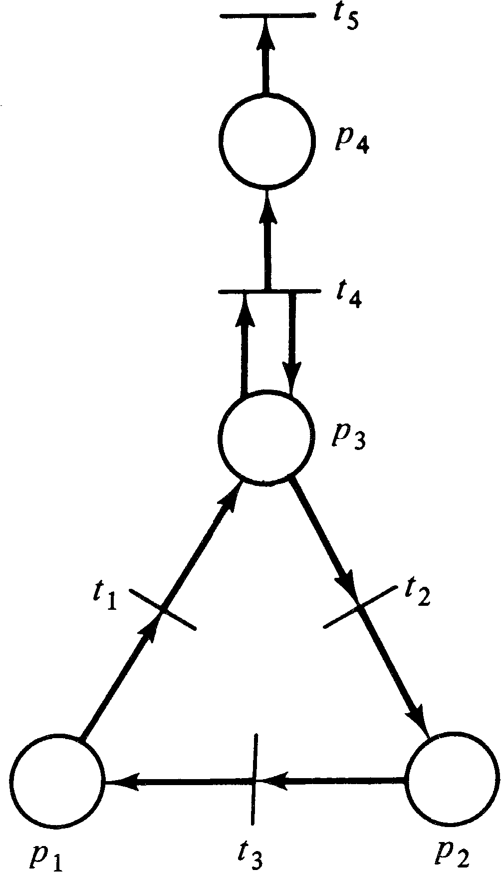
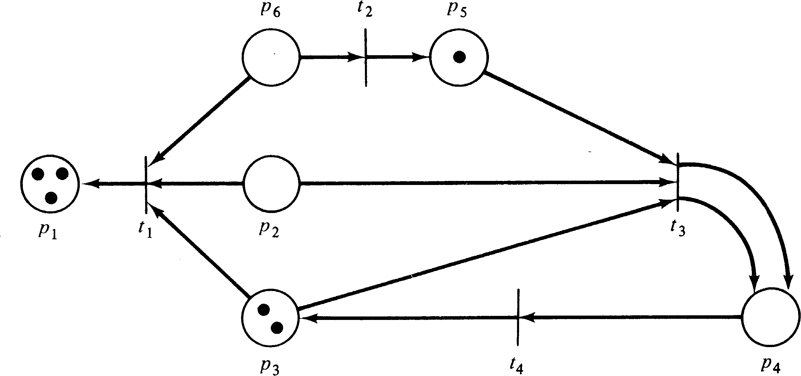
Figures 2.4, 2.5, and 2.6 are Petri net graphs equivalent to
the Petri net structures of Figures 2.1, 2.2, and 2.3.

To demonstrate the equivalence of these two representations of a Petri net, the Petri net structure and the Petri net graph, we show how to transform one into the other. Assume we are given a Petri net structure C = (P, T, I, O) with P = { p1, p2, …, pn } and T = { t1, t2, …, tm } . Then we can define a Petri net graph as follows,
| #((pi, tj), A) | = | #(pi, I(tj)) |
| #((tj, pi), A) | = | #(pi, O(tj)) |
Conversion in the opposite direction (from a Petri net graph to a Petri net structure) is similar, and we leave the detailed description to the reader. One interesting problem arises in the translation from a Petri net graph to a Petri net structure. If the set of vertices is partitioned into the two sets S and R, which set should be the places and which set should be the transitions? Both possible selections allow a Petri net to be defined, although the two resulting structures have interchanged places and transitions.
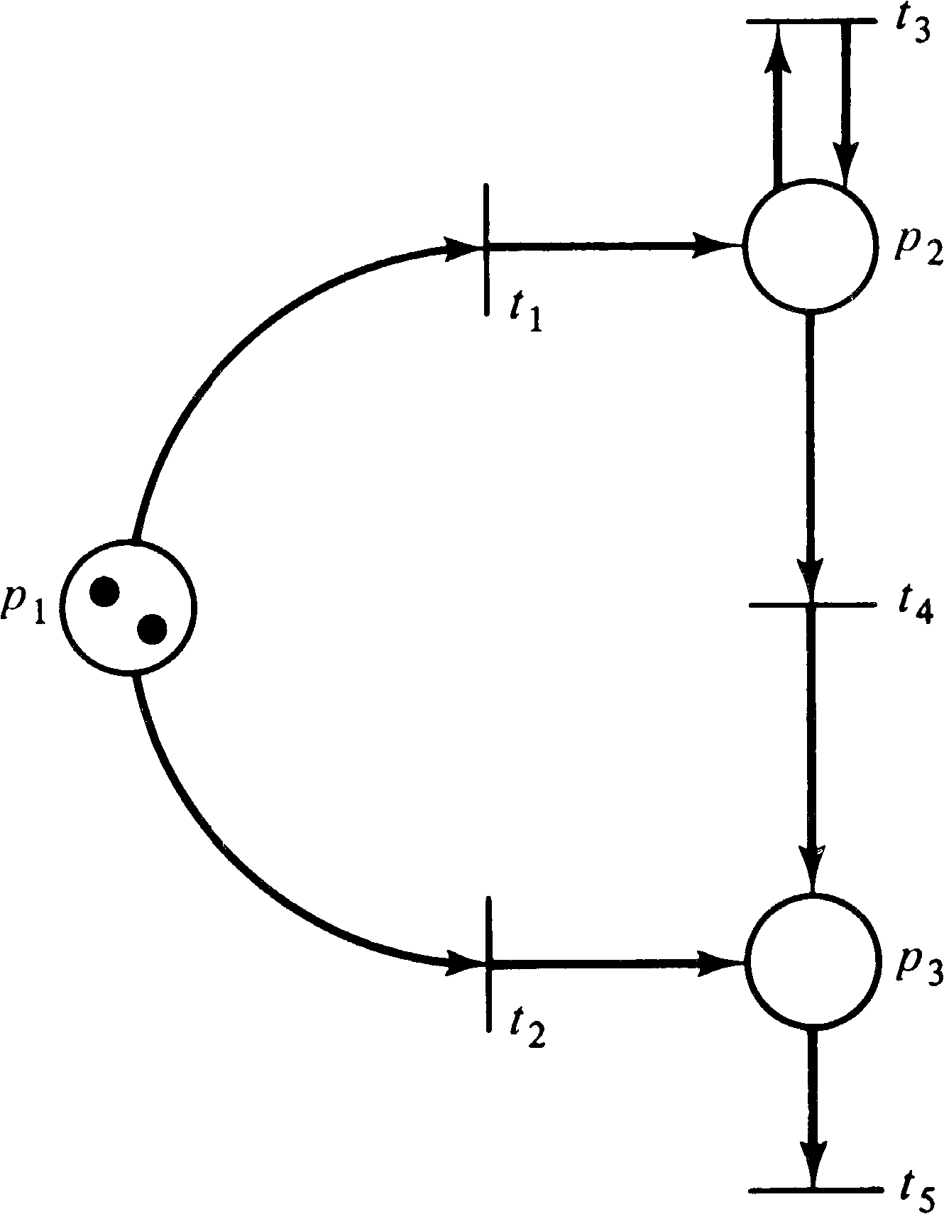
The dual of a Petri net C = (P, T, I, O) is the Petri
net C = (T, P, I, O) which results from interchanging
places and transitions. The graph structure is maintained,
simply interchanging the circles and bars of the graph to
indicate the change in places and transitions (but see
Exercise 6). Figure 2.7 is
the dual of the Petri net of Figure 2.4. Duality is a
commonly used aspect of graph theory and would appear to be
an interesting Petri net concept. However, no use has been
made of the concept of the dual of a Petri net in Petri net
research. This results, most likely, from the difficulty of
defining the dual of a marked Petri net. Marked Petri nets
are discussed next.
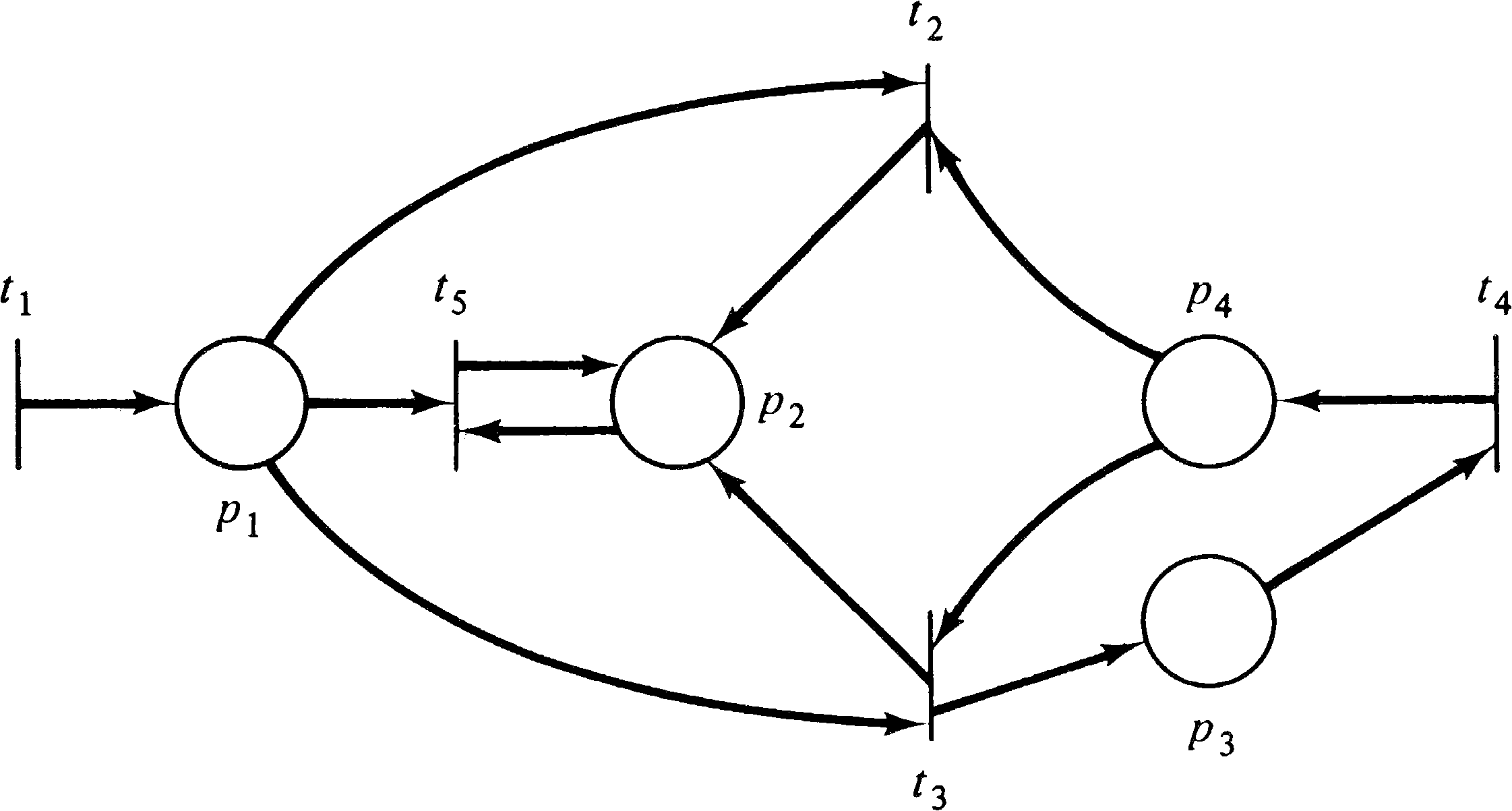
| P | = | { p1, p2, p3, p4 } | ||||
| T | = | { t1, t2, t3, t4, t5 } | ||||
| I(t1) | = | { } | O(t1) | = | { p1 } | |
| I(t2) | = | { p1 } | O(t2) | = | { p2 } | |
| I(t3) | = | { p2, p4 } | O(t3) | = | { p1, p3 } | |
| I(t4) | = | { } | O(t4) | = | { p3 } | |
| I(t5) | = | { p3 } | O(t5) | = | { p4 } |
| P | = | { p1, p2 } | ||||
| T | = | { t1, t2, t3 } | ||||
| I(t1) | = | { p1 } | O(t1) | = | { p1, p2 } | |
| I(t2) | = | { p1 } | O(t2) | = | { p2 } | |
| I(t3) | = | { p2 } | O(t3) | = | { } |
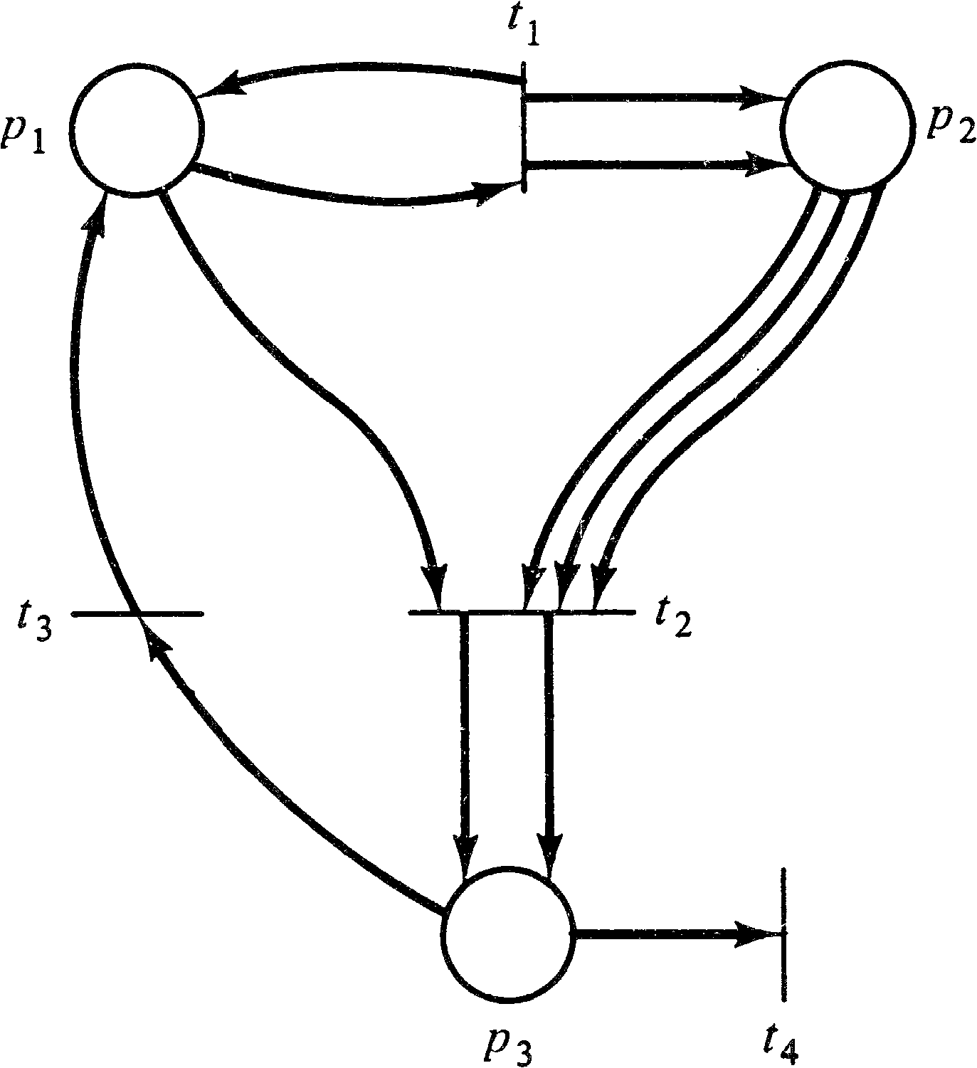

| P | = | { p1, p2, p3, p4 } | ||||
| T | = | { t1, t2, t3, t4 } | ||||
| I(t1) | = | { } | O(t1) | = | { p1, p1, p1, p1, p2 } | |
| I(t2) | = | { p2 } | O(t2) | = | { p1, p1, p1, p1, p1, p1, p3 } | |
| I(t3) | = | { p1, p1, p1, p1, p1, p1 } | O(t3) | = | { p2, p2, p2, p2, p4, p4 } | |
| I(t4) | = | { p3, p4, p4, p2 } | O(t4) | = | { } |
A marking μ is an assignment of tokens to the places of a Petri net. A token is a primitive concept for Petri nets (like places and transitions). Tokens are assigned to and can be thought to reside in the places of a Petri net. The number and position of tokens may change during the execution of a Petri net. The tokens are used to define the execution of a Petri net.
The marking μ can also be defined as an n -vector, μ = ( μ1, μ2, …, μn ), where n = | P | and each μi ∈ N, i = 1, …, n. The vector μ gives for each place pi in a Petri net the number of tokens in that place. The number of tokens in place pi is μi, i = 1, …, n. The definitions of a marking as a function and as a vector are obviously related by μ ( pi ) = μi. The functional notation is somewhat more general and so is more commonly used.
A marked Petri net M = ( C, μ ) is a Petri net structure C = (P, T, I, O) and a marking μ . This is also sometimes written as M = (P, T, I, O, μ ) .
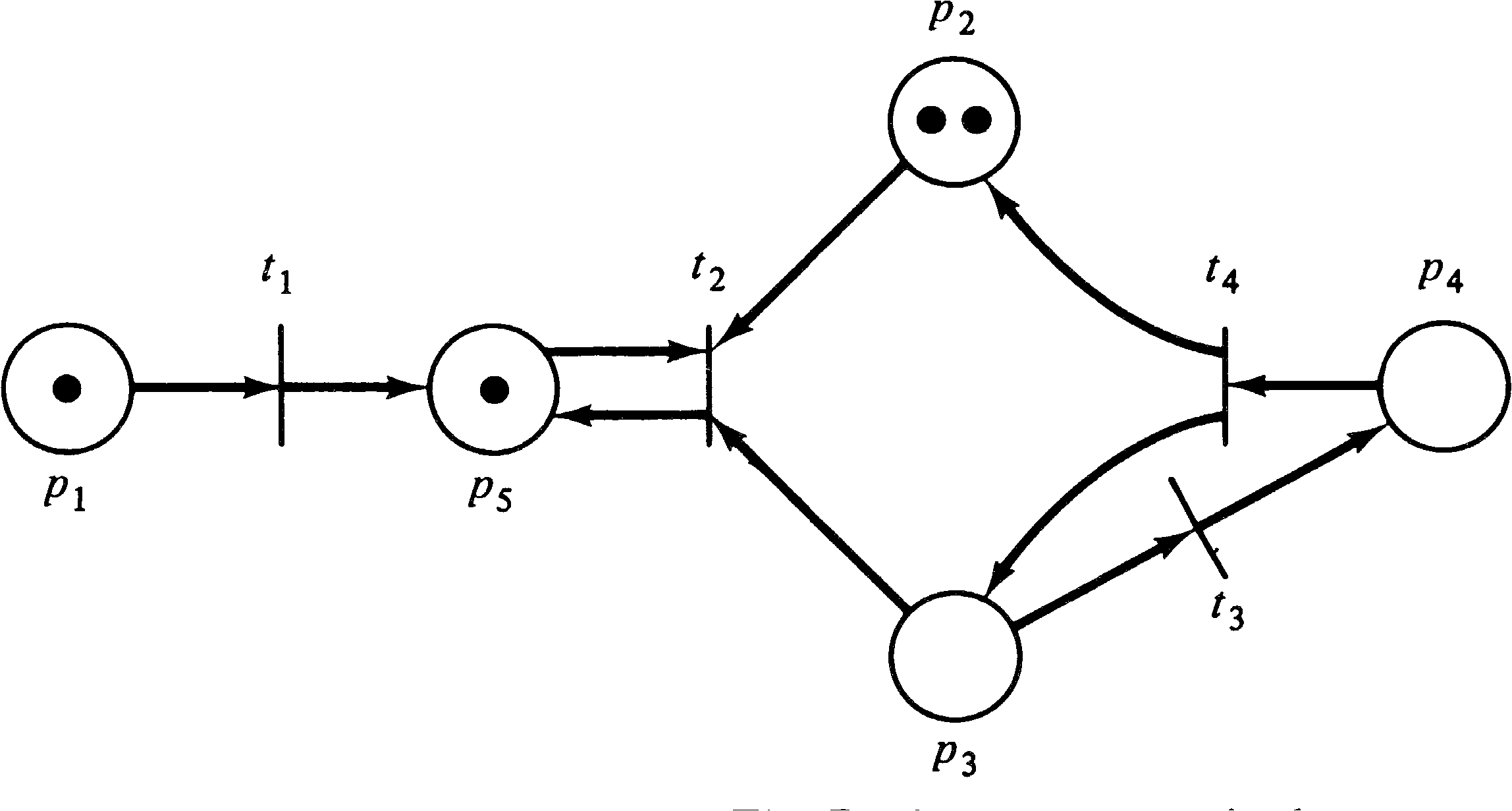
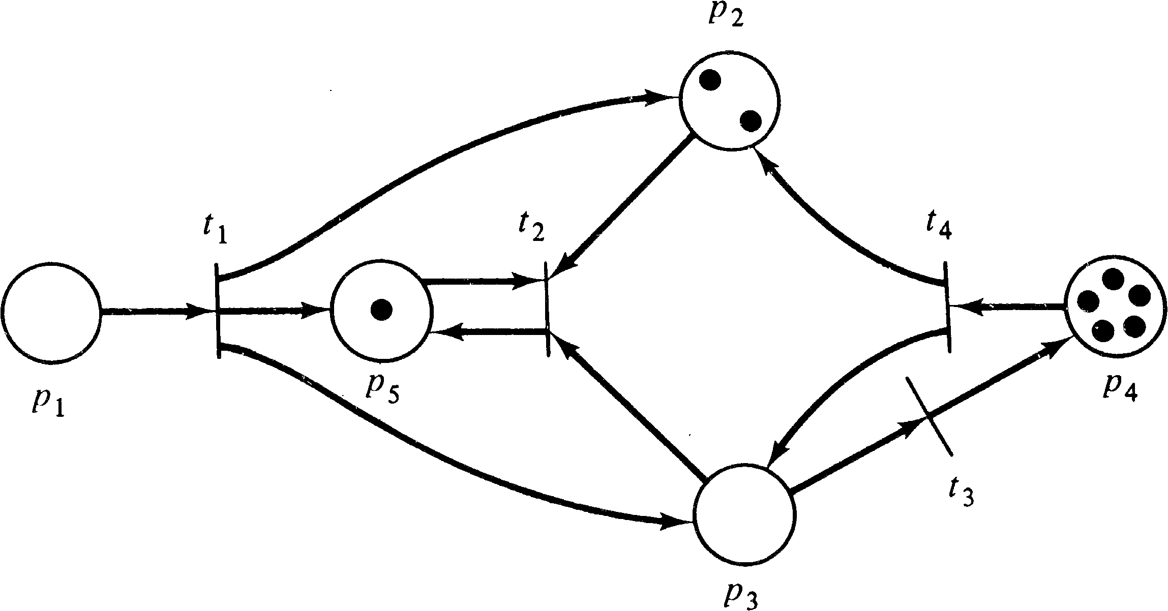
On a Petri net graph, tokens are represented by small dots
∙ in the circles which represent the places of a Petri
net. Figures 2.11 and 2.12 show examples of a graph
representation of a marked Petri net.
Since the number of tokens which may be assigned to a place
of a Petri net is unbounded, there are an infinity of
markings for a Petri net. The set of all markings for a
Petri net with n places is simply the set of all
n -vectors, Nn. This set, although infinite,
is of course denumerable.
Exercises
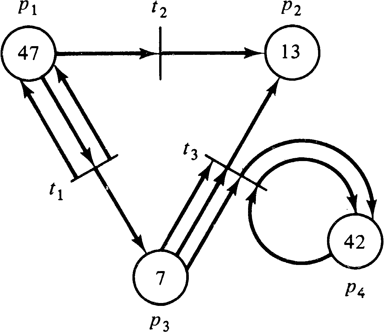
The execution of a Petri net is controlled by the number and distribution of tokens in the Petri net. Tokens reside in the places and control the execution of the transitions of the net. A Petri net executes by firing transitions. A transition fires by removing tokens from its input places and creating new tokens which are distributed to its output places.
A transition may fire if it is enabled. A transition is enabled if each of its input places has at least as many tokens in it as arcs from the place to the transition. Multiple tokens are needed for multiple input arcs. The tokens in the input places which enable a transition are its enabling tokens. For example, if the inputs to transition t4 are places p1 and p2, then t4 is enabled if p1 has at least one token and p2 has at least one token. For a transition t7 with input bag { p6, p6, p6 }, place p6 must have at least three tokens to enable t7.
| μ(pi) ≥ #(pi, I(tj)) |
A transition fires by removing all of its enabling tokens from its input places and then depositing into each of its output places one token for each arc from the transition to the place. Multiple tokens are produced for multiple output arcs. A transition t3 with I ( t3 ) = { p2 } and O ( t3 ) = { p7, p13 } is enabled whenever there is at least one token in place p2. Transition t3 fires by removing one token from place p2 and depositing one token in place p7 and one token in place p13 (its outputs). Extra tokens in place p2 are not affected by firing t3 (although they may enable additional firings of t3 ). A transition t2 with I ( t2 ) = { p21, p23 } and O ( t2 ) = { p23, p25, p25 } fires by removing one token from p21 and one token from p23 and then deposits one token in p23 and two tokens in p25 (since p25 has a multiplicity of two).
Firing a transition will in general change the marking μ of the Petri net to a new marking, μ′ . Notice that since only enabled transitions may fire, the number of tokens in each place always remains nonnegative when a transition is fired. Firing a transition can never try to remove a token which is not there. If there are not enough tokens in any input place of a transition, then the transition is not enabled and cannot fire.
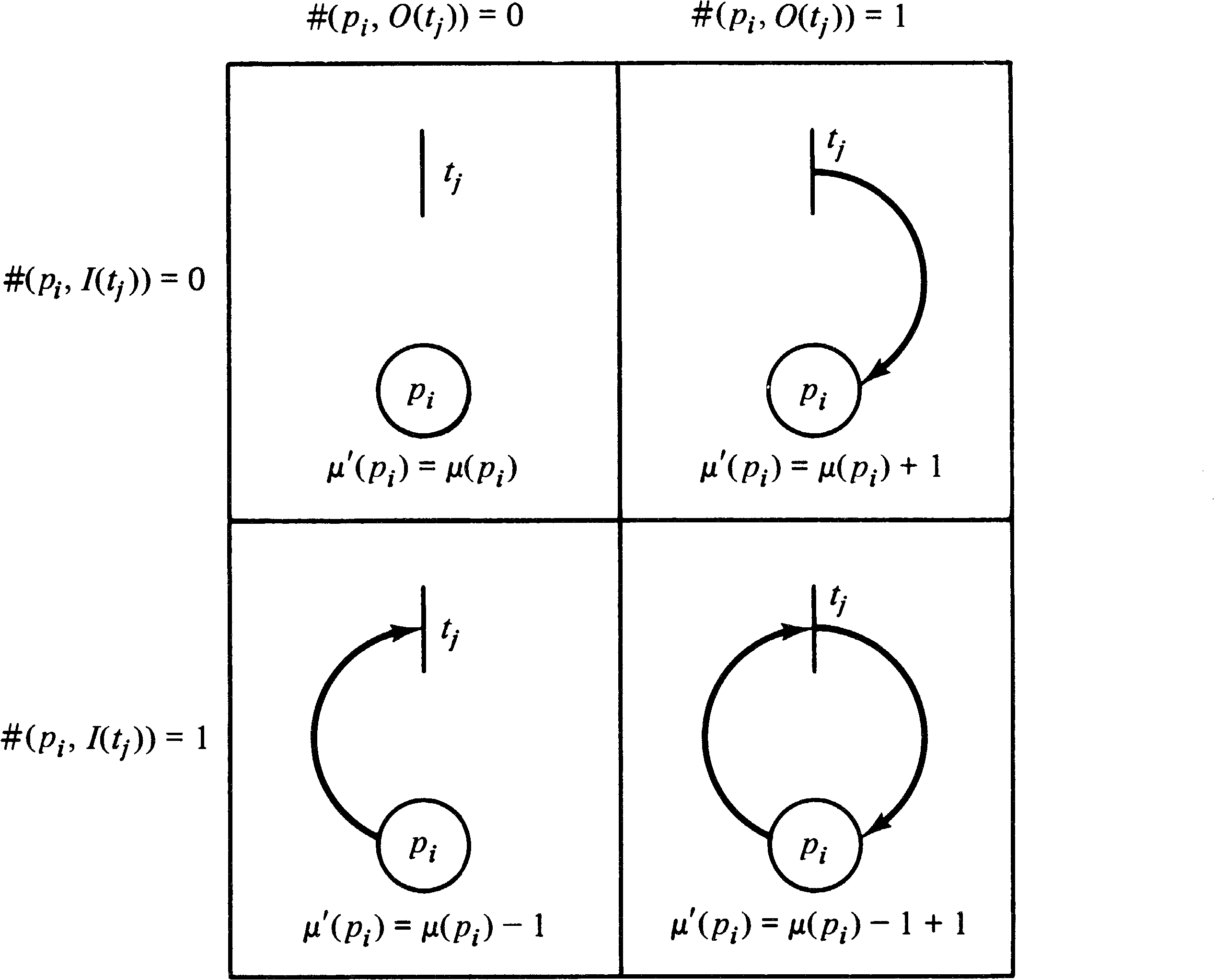
| μ′(pi) | = | μ(pi) − #(pi, I(tj)) + #(pi, O(tj)) |
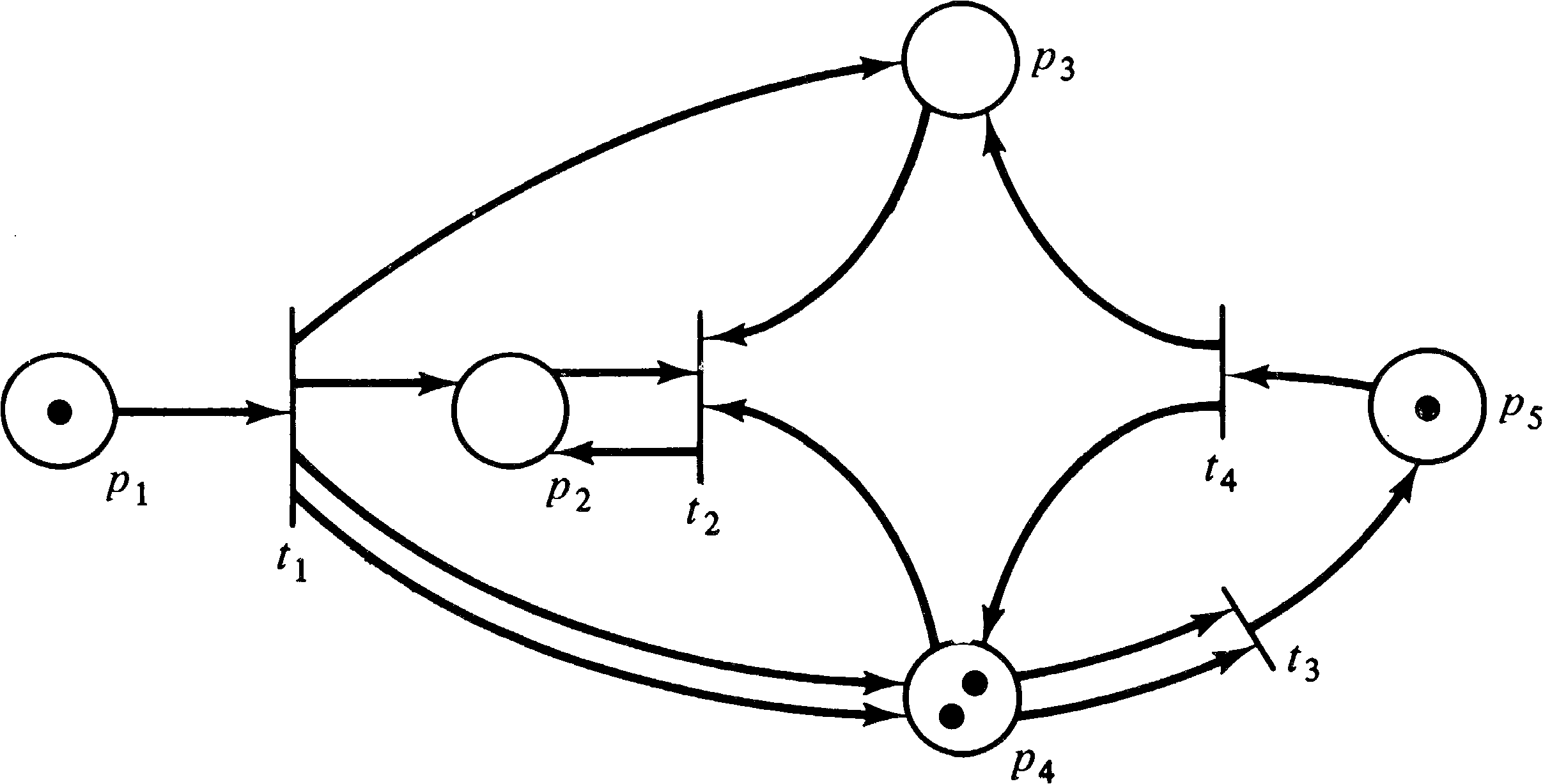
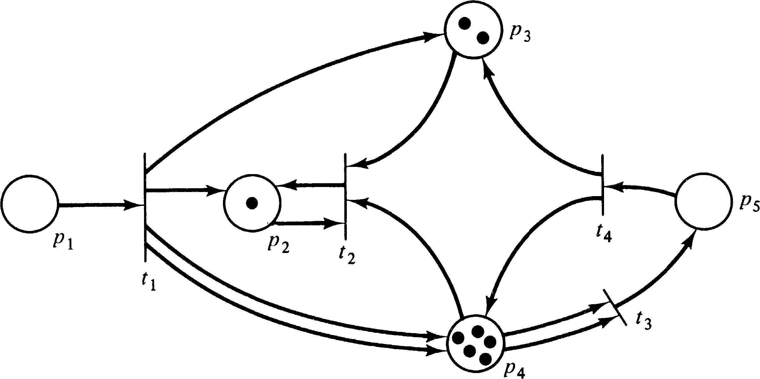
As an example, consider the marked Petri net of Figure 2.15.
With this marking, three transitions are enabled,
transitions t1, t3, and t4.
Transition t2 is not enabled because there is no
token in either place p2 or p3, which are
both inputs of transition t2. Since transitions
t1, t3, and t4 are enabled, any
of them may fire. If transition t4 fires, it
removes a token from each input and deposits a token in each
output. This removes the token in p5, deposits
one token in p3, and increases the number of
tokens in p4 from two to three. Thus, the new
marking which results from firing transition t4 is
shown in Figure 2.16.
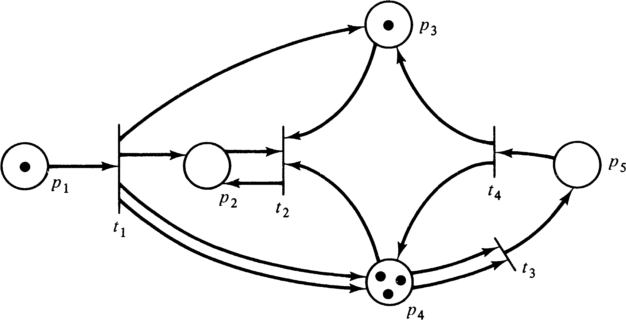
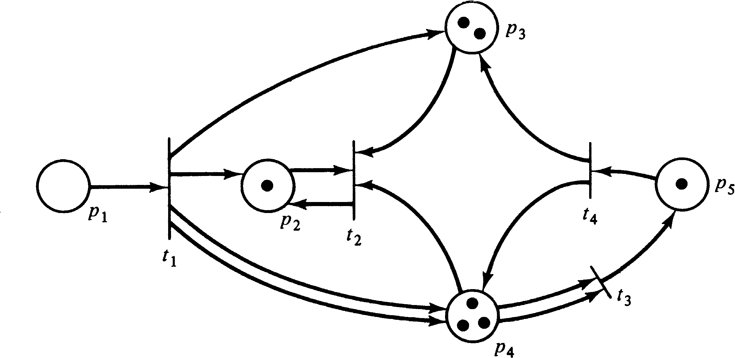
In the marked Petri net of Figure 2.16, only transitions
t1 and t3 are enabled. Firing
transition t1 will remove the token in p1
and deposit tokens in p2, p3, and
p4 (two tokens in p4 since it is a
multiple output of transition t1 ). This produces
the marking of Figure 2.17. In this marked Petri net,
transitions t2 and t3 are enabled.
Firing transition t3 produces the marking of
Figure 2.18 where two tokens have been removed from
p4 and one has been added to p5.
Transition firings can continue as long as there exists at
least one enabled transition. When there are no enabled
transitions, the execution halts.
Exercises
The state of a Petri net is defined by its marking. The firing of a transition represents a change in the state of the Petri net by a change in the marking of the net. The state space of a Petri net with n places is the set of all markings, that is, Nn. The change in state caused by firing a transition is defined by a change function δ called the next-state function. When applied to a marking (state) μ and a transition tj this function yields the new marking (state) which results from firing transition tj in marking μ . Since tj can fire only if it is enabled, δ ( μ, tj ) is undefined if tj is not enabled in marking μ . If tj is enabled, then δ ( μ, tj ) = μ′, where μ′ is the marking which results from removing tokens from the inputs of tj and adding tokens to the outputs of tj.
| μ(pi) ≥ #(pi, I(tj)) |
| μ′(pi) | = | μ(pi) − #(pi, I(tj)) + #(pi, O(tj)) |
Given a Petri net C = (P, T, I, O) and an initial marking μ0, we can execute the Petri net by successive transition firings. Firing an enabled transition tj in the initial marking produces a new marking μ1 = δ ( μ0, tj ) . In this new marking, we can fire any new enabled transition, say tk, resulting in a new marking μ2= δ ( μ1, tk ) . This can continue as long as there is at least one enabled transition in each marking. If we reach a marking in which no transition is enabled, then no transition can fire, the next-state function is undefined for all transitions, and the execution must halt.
Two sequences result from the execution of a Petri net: the sequence of markings ( μ0, μ1, μ2, …) and the sequence of transitions which were fired ( tj0, tj1, tj2, …) . These two sequences are related by the relationship δ ( μk, tjk ) = μk + 1 for k = 0, 1, 2, … . Given a transition sequence and μ0, we can easily derive the marking sequence for the execution of the Petri net, and, except for a few degenerate cases, given the marking sequence, we can derive the transition sequence. Both of these sequences thus provide a record of the execution of the Petri net.
In a marking μ, a set of transitions will be enabled and may fire. The result of firing a transition in a marking μ is a new marking μ′ . We say that μ′ is immediately reachable from μ ; that is, we can immediately get to state μ′ from state μ .

It is convenient to extend the next-state function to map a marking and a sequence of transitions into a new marking. For a sequence of transitions tj1 tj2... tjk and marking μ, the marking μ′ = δ ( μ, tj1 tj2 ⋯ tjk ) is the result of firing first tj1, then tj2, and so on until tjk is fired. (This is possible, of course, only if each transition is enabled when it is to be fired.)
| δ(μ, tj σ) | = | δ(δ(μ, tj), σ) |
| δ(μ, λ) | = | μ |
| ∪ | R ( C, μ ) = Nn. |
| μ ∈ Nn |
| R ( C, μ ) | = | ∪ | δ ( μ, tj ) ? |
| tj ∈ T |
| R ( C, μ ) | = | ∪ | R ( C, δ ( μ, tj )) ? |
| tj ∈ T |
The theory of Petri nets has been developed by a number of people working at different times in different places with different backgrounds and motivations. In part due to this diversity, many of the fundamental concepts have been defined by different researchers in different ways. We present some of these variant definitional forms here to show that there is no substantial difference in the definitions and to prepare the reader for the varying representations which may be encountered in the literature.
Petri's original nets [Petri 1962a], for example, did not allow multiple arcs between places and transitions. This is equivalent to defining the inputs and outputs of a transition to be sets (not bags) of places. Further, the firing rule was limited to requiring that a token reside in each input place to a transition and no tokens reside in the output places. A transition fired by removing the tokens from its inputs (which now became empty) and placing tokens in the (previously empty) outputs (which now became full). A transition could not fire if a token already resided in an output place. Thus a marking assigned either zero or one token to each place, μ: P → { 0, 1 } . It should be obvious then that a net with only n places has exactly 2n possible markings, a finite number of states.
The early work at ADR by Holt and the Information System Theory Project [Holt et al. 1968] continued with these same definitions, but as work progressed, the limitations of this model were recognized. The work of Holt and Commoner presented at the Woods Hole conference [Holt and Commoner 1970] generalized the class of markings and the firing rule to allow arbitrary markings, μ: P → { 0, 1, 2, … } . This then defined the basic Petri net model as it is defined today (with the exception of the multiple arc feature).
Many of the early researchers did not formally define their models but rather described informally the relevant components, such as places, transitions, tokens, and the firing rule. One of the first formal definitions was by Patil [1970a] in his Ph.D. dissertation where a Petri net was defined as a four-tuple (T, P, A, B) with T the set of transitions, P the set of places, A a set of arcs, and B an initial marking. The arcs in the set A connected either a place with a transition or a transition with a place. Thus A ⊆ (P ⨯ T) ∪ (T ⨯ P) . Many papers on Petri nets are based on this definition and define a Petri net as a triple (P, T, A) with a separate marking function.
The conversion from the (P, T, A) form of definition to separate input and output functions is relatively straightforward. The set of arcs A is split into a set of input arcs { ( pi, tj ) | ( pi, tj ) ∈ A } and output arcs { ( tj, pi ) | ( tj, pi ) ∈ A } . This form leads directly to the generalization allowing multiple inputs and outputs. It is necessary simply to attach a multiplicity to each input or output arc.
Hack [1975c] eventually settled on a definition of Petri nets as a four-tuple (P, T, F, B), with P the set of places and T the set of transitions, as usual. F and B are functions mapping places and transitions onto the number of tokens needed for input ( F ) or produced for output ( B ). Thus a transition tj can fire only if at least F ( tj, pi ) tokens are in each place pi ∈ P. A transition fires by removing F ( tj, pi ) tokens from each input place and depositing B ( tj, pi ) tokens in each output place. The functions F and B can be represented by matrices.
Peterson in his dissertation [Peterson 1973] tried to combine transitions and their inputs and outputs by defining a transition as an ordered pair of bags of places, tj ∈ P∞ ⨯ P∞. The first component of the pair is the bag of inputs to the transition; the second component is the bag of outputs of the transition. This reduced the primitive concepts of the theory to places and tokens, since transitions are structures composed of places. It was particularly useful in allowing the easy definition of a transition for a constructed Petri net.
These definitions vary from the one presented here only by
notational differences. For most work on Petri nets, this
is the case: The differences in definition are strictly
notational. However in some cases, the definitions may
restrict the class of Petri nets by not allowing multiple
input or output arcs or otherwise restricting the form of
the transitions; e.g., transitions are required to
have a nonnull set of input places and a nonnull set of
output places, or the input and output places of a
transition must be disjoint (self-loop-free). Even these
differences are not important, as is seen in Chapter 5.
Exercises
Few descriptions of Petri nets concentrate simply on the
basic definitions. The Computing Surveys tutorials by
Baer [1973a] and Peterson [1977] are probably the best bets
for continued introduction. Almost any paper on Petri nets
will present the basic definitions and notation in the first
few sections. Hence you could simply scan the beginning of
some of the papers listed in the bibliography to find a
variety of definitions. Try Holt et al. [1968], Holt and
Commoner [1970], Hack [1974a; 1975b; 1975c], Keller [1975a],
Misunas [1973], Murata [1977a], and Thomas [1976].
2.8. Topics for Further Study
| Home | Comments? |