| Home | Up | Questions? |
Petri nets were designed for and are used mainly for modeling. Many systems, especially those with independent components, can be modeled by a Petri net. The systems may be of many different kinds: computer hardware, computer software, physical systems, social systems, and so on. Petri nets are used to model the occurrence of various events and activities in a system. In particular, Petri nets may model the flow of information or other resources within a system.
In this chapter, we present several examples of the types of
systems which have been modeled by Petri nets. From this
presentation, you will gain an understanding of the large
class of systems which can be modeled by Petri nets, some of
the modeling techniques which are used, and some of the
properties which are desired for the modeled systems.
3.1. Events and Conditions
The simple Petri net view of a system concentrates on two primitive concepts: events and conditions. Events are actions which take place in the system. The occurrence of these events is controlled by the state of the system. The state of the system can be described as a set of conditions. A condition is a predicate or logical description of the state of the system. As such, a condition may either hold (be true) or not hold (be false).
Since events are actions, they may occur. For an event to occur, it may be necessary for certain conditions to hold. These are the preconditions of the event. The occurrence of the event may cause the preconditions to cease to hold and may cause other conditions, postconditions, to become true.
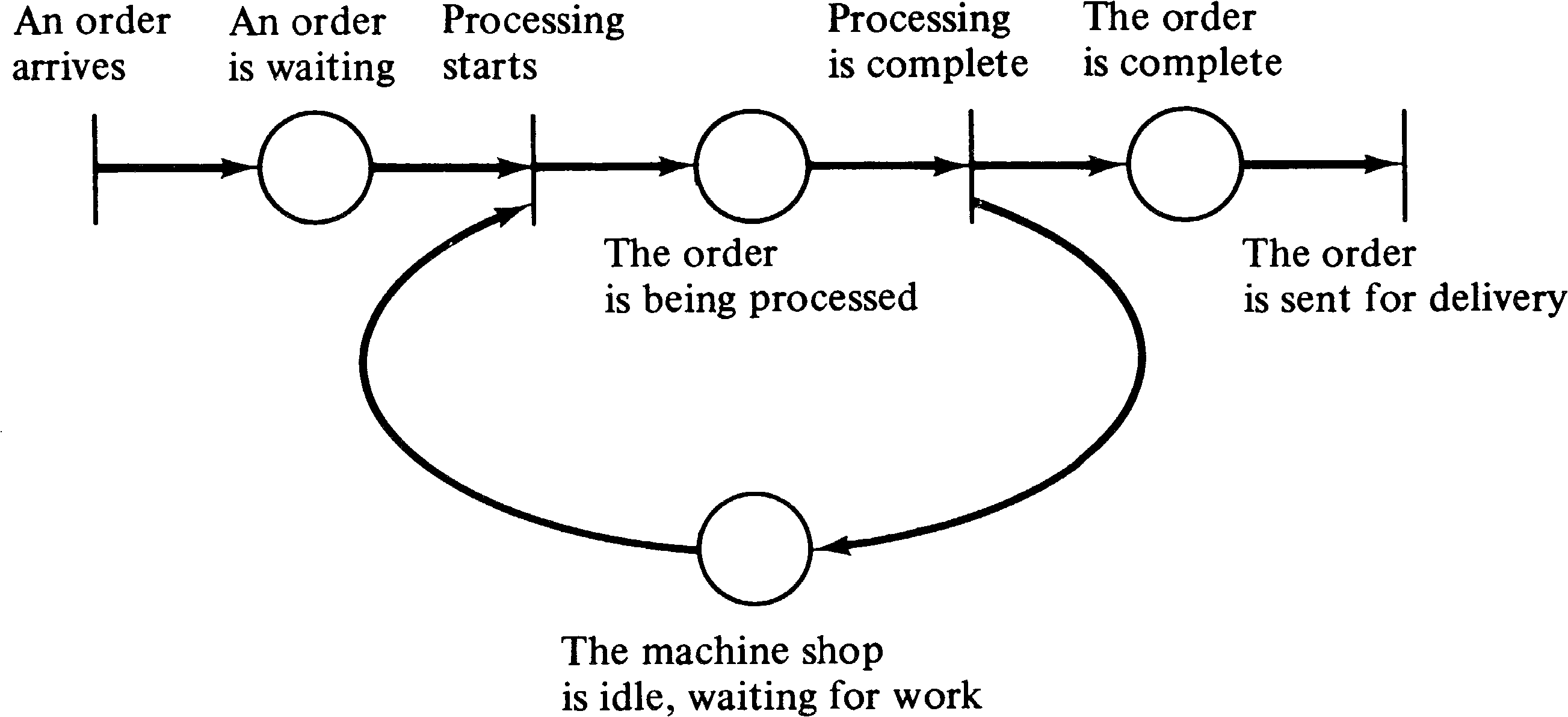
As an example, consider a simple machine shop modeling problem. The machine shop waits until an order appears and then machines the ordered part and sends it out for delivery. The conditions for the system are
| event | preconditions | postconditions |
| 1 | none | b |
| 2 | a, b | c |
| 3 | c | d, a |
| 4 | d | none |
This view of a system can be easily modeled as a Petri net. Conditions are modeled by places in a Petri net; events are modeled by transitions. The inputs of a transition are the preconditions of the corresponding event; the outputs are the postconditions. The occurrence of an event corresponds to the firing of the corresponding transition. The holding of a condition is represented by a token in the place corresponding to the condition. When the transition fires it removes the enabling tokens representing the holding of the preconditions and creates new tokens which represent the holdings of postconditions.
The Petri net of Figure 3.1 is a Petri net model of the
machine shop example given above. We have labeled each
transition and place with the corresponding event or
condition.

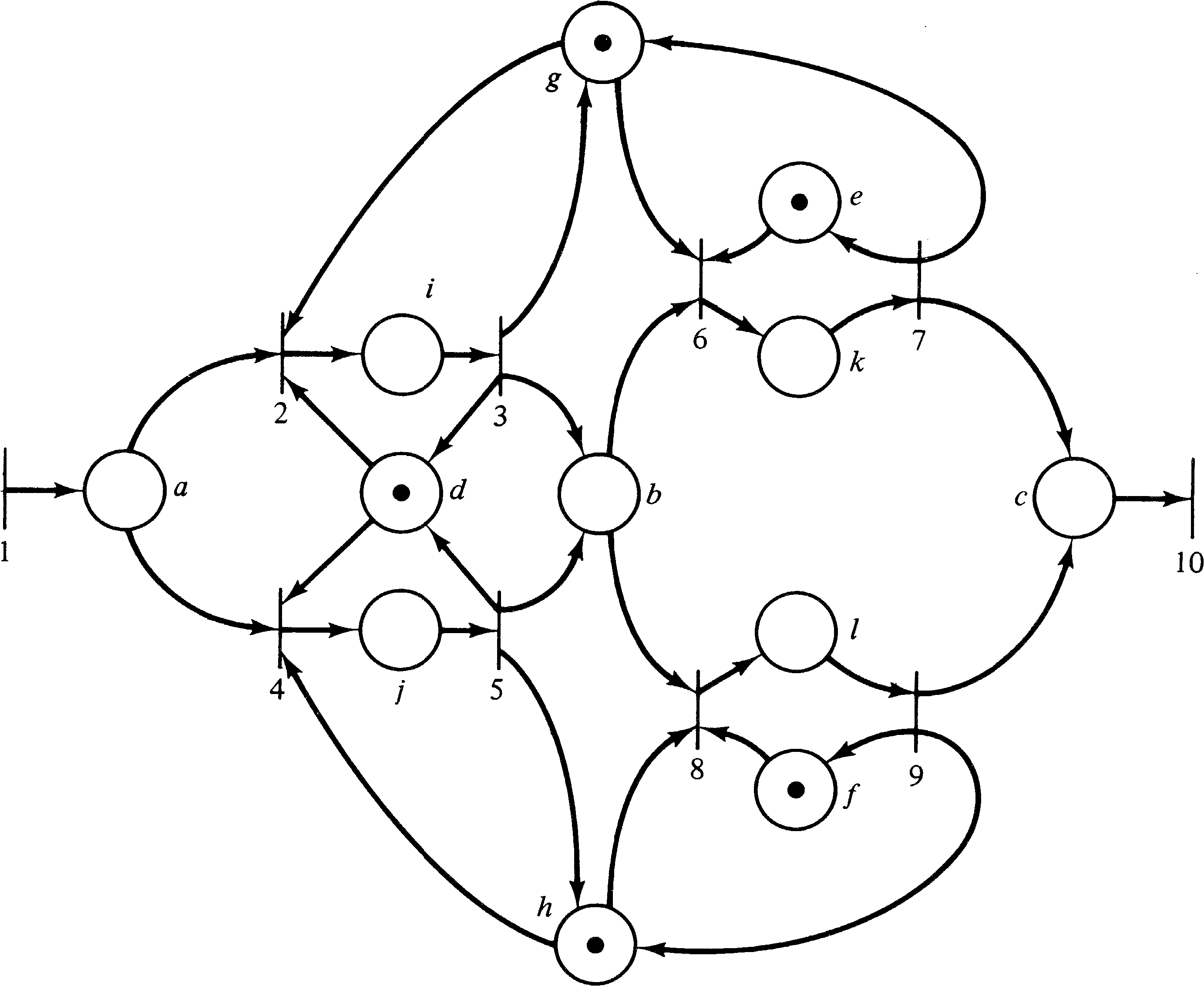
More complicated systems can also be modeled. The machine shop may have three different machines, M1, M2, and M3 and two operators, F1 and F2. Operator F1 can operate machines M1 and M2 while operator F2 can operate machines M1 and M3. Orders require two stages of machining. First they must be machined by machine M1 and then by either machine M2 or M3. This more complex system would have the following conditions.
The preconditions and postconditions of each event are
| event | preconditions | postconditions |
| 1 | none | a |
| 2 | a, g, d | i |
| 3 | i | g, d, b |
| 4 | a, h, d | j |
| 5 | j | b, h, d |
| 6 | b, g, e | k |
| 7 | k | c, g, e |
| 8 | b, f, h | l |
| 9 | l | c, f, h |
| 10 | c | none |
The Petri net for this system is shown in Figure 3.2.
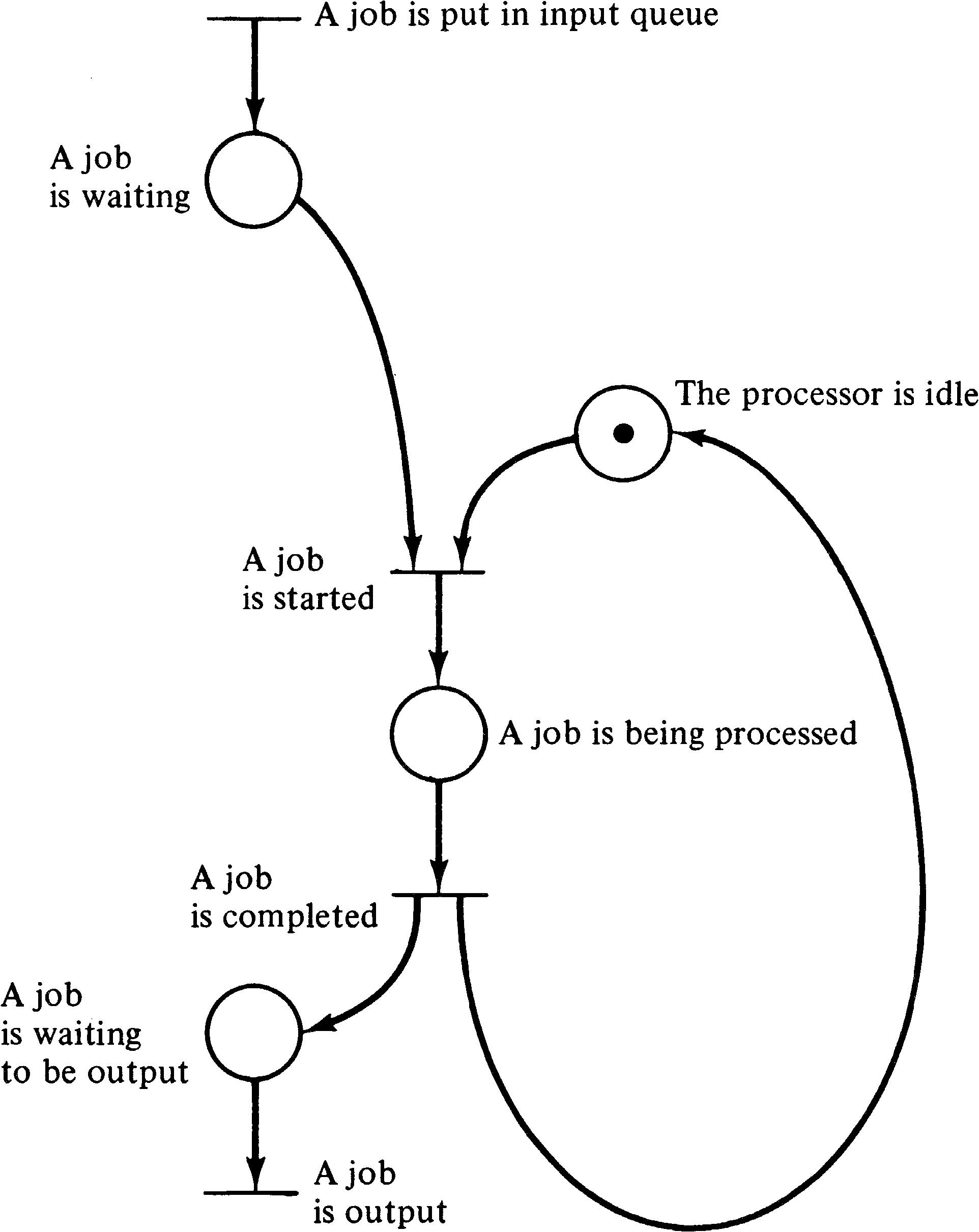
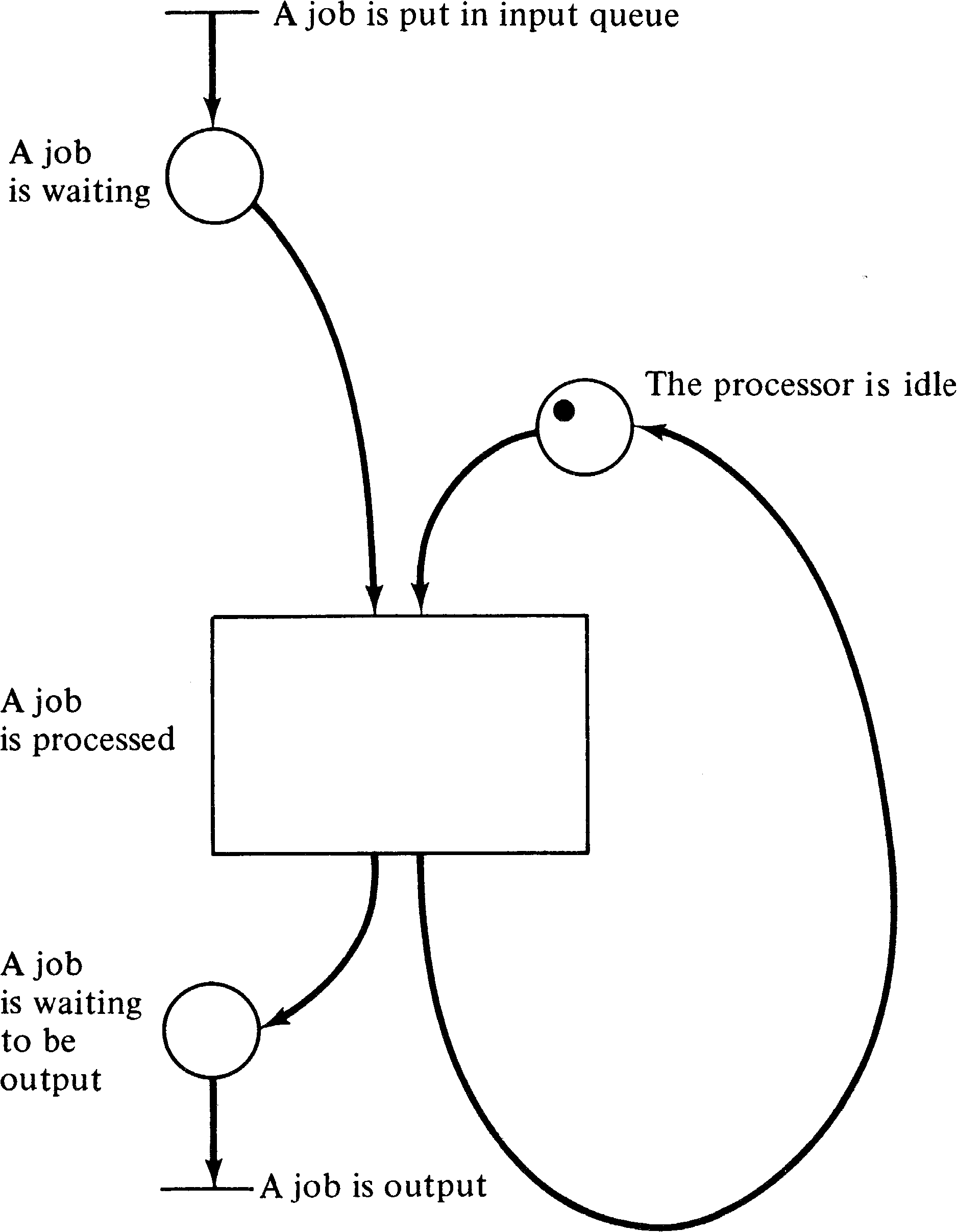
A similar example can be drawn from a computer system which
processes jobs from an input device and outputs the results
on an output device. Jobs appear on the input device. When
the processor is free and there is a job on the input
device, the processor starts to process the job. When the
job is complete, it is sent to the output device; the
processor either continues with another job if one is
available or waits until one arrives if there is no job yet
on the input device. This system can be modeled by the
Petri net of Figure 3.3.
These examples illustrate several points about Petri nets and the systems which they can model. One is the inherent parallelism or concurrency. In the Petri net model, two events which are both enabled and do not interact may occur independently. There is no need to synchronize events unless it is required by the underlying system which is being modeled. When synchronization is needed, it is easy to model this also. Thus, Petri nets would seem ideal for modeling systems of distributed control with multiple processes executing concurrently in time.
Another major feature of Petri nets is their asynchronous nature. There is no inherent measure of time or the flow of time in a Petri net. This reflects a philosophy of time which states that the only important property of time, from a logical point of view, is in defining a partial ordering of the occurrence of events. Events take variable amounts of time in real life, and this variability is reflected in the Petri net model by not depending on a notion of time to control the sequence of events. The Petri net structure itself contains all necessary information to define the possible sequences of events. Thus, in Figure 3.3, the event “A job is completed” must follow the corresponding “A job is started” event. However, no information at all is given or needed concerning the amount of time to execute a job.
A Petri net execution (and the system behavior which it models) is viewed here as a sequence of discrete events. The order of occurrence of the events is one of possibly many allowed by the basic structure. This leads to an apparent nondeterminism in Petri net execution. If, at any time, more than one transition is enabled, then any of the several enabled transitions may be “the next” to fire. From the point of view of the classical execution model, the choice as to which transition fires is made in a nondeterministic manner, i.e., randomly. This feature of Petri nets reflects the fact that in real life situations in which several things are happening concurrently, the apparent order of occurrence of events is not unique, but rather any of a set of sequences of events may occur. However, the partial ordering in which events occur is unique.
The questions involved with these concepts can get quite philosophical in nature. For example, I, personally, tend toward a deterministic view of the universe: All actions are predetermined by the state of the universe, and there is no randomness. Randomness is merely a result of incomplete knowledge of the state of the universe and its individual transitions. In this sense, the selection of one of a set of enabled transitions to fire is determined in the modeled system, but not in the model simply because the model does not represent the complete information about the system.
The theory of relativity should also be considered. One of the basic tenets of relativity theory is that communication is not instantaneous, but rather the information about the occurrence of an event propagates through space at a speed limited by the speed of light, c. The meaning of this is that if two events can occur simultaneously, that is, with no causal relationship, then the order of occurrence may appear different for two separate observers. For two events A and B which occur at essentially the same time, an observer stationed near event A would receive the information concerning event A before the information concerning event B could propagate to the observer. The observer would then deduce that event A occurred before event B. A separate observer stationed near B, on the other hand, could determine that exactly the opposite sequence of events occurred.
These considerations, although necessary for a complete understanding of events, introduce considerable complexity in the description and analysis of the dynamic behavior of a Petri net when viewed as a sequence of transition firings. To help limit this complexity, one limitation in the modeling of systems by Petri nets is generally accepted. The firing of a transition (and the associated event) is considered to be an instantaneous event, taking zero time, and the occurrences of two events cannot happen simultaneously. The events modeled are called primitive events; primitive events are instantaneous and nonsimultaneous. (It is sometimes argued that time is a continuous real variable. Hence if we assign a time of occurrence to each event, the probability of any two separately chosen continuous real variables being identically equal is zero, and hence events are nonsimultaneous.)
A nonprimitive event is an event which does not take zero
time. Nonprimitive operations are not nonsimultaneous and
hence may overlap in time. Since most events in the real
world take time, they are nonprimitive events and hence
cannot be properly modeled by transitions in a Petri net.
However this need not cause problems in the modeling of a
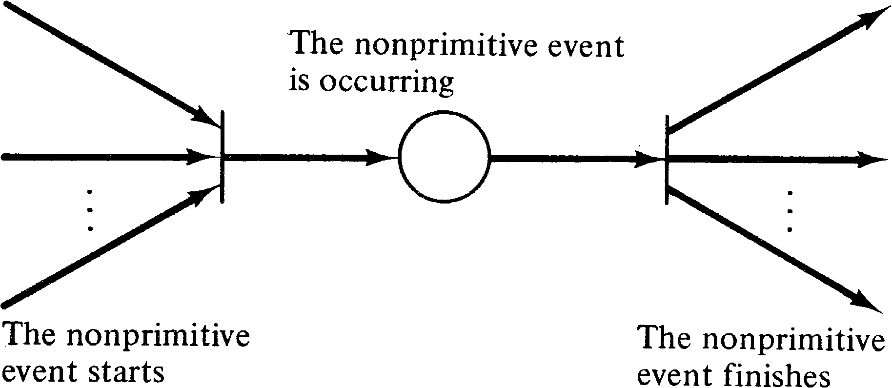
system. A nonprimitive event can be decomposed into two
primitive events, “The nonprimitive event starts”
and “The nonprimitive event finishes,”
and a condition, “The nonprimitive event is occurring.”
This can be modeled as
shown in Figure 3.4.
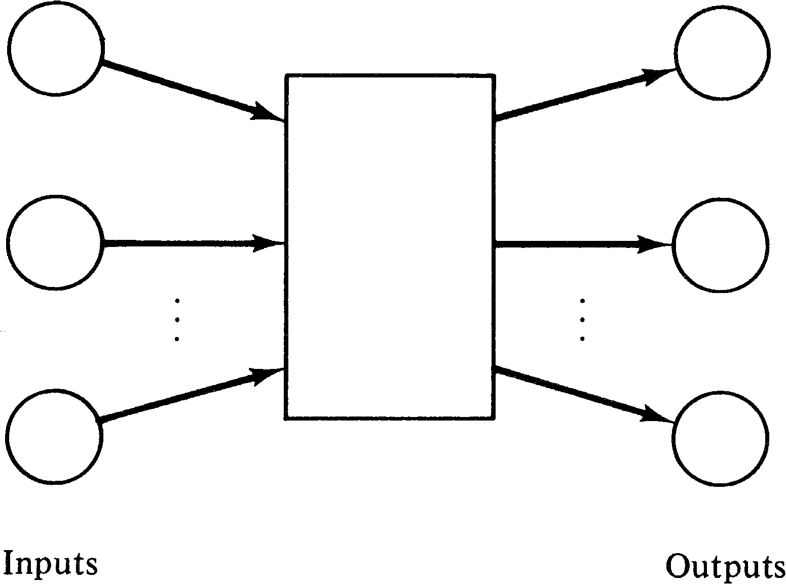
Petri and others have suggested that nonprimitive events
should be represented by a box in a Petri net [Petri 1975]
as shown in Figure 3.5, with primitive events represented by
bars, as we have in the past. This would simplify some
Petri nets, such as Figure 3.6, which is equivalent to the
Petri net of Figure 3.3. However, since the suggested
concept can, in principle, be explained in terms of more
primitive constructs, we do not use the box notation in this
text. The box notation can be of considerable value when
modeling a complex system at several hierarchical levels,
since it allows entire subnets to be abstracted to a single
element of the net. It is in some sense similar to the
subroutine or macro concept of programming languages.
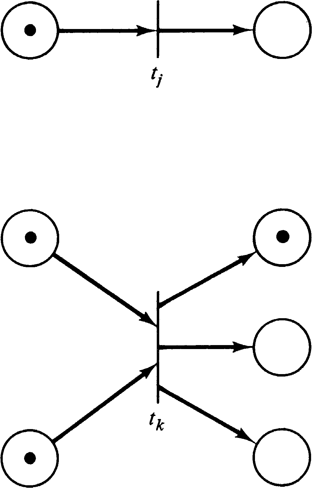
The nondeterministic and nonsimultaneous firing of
transitions in the modeling of concurrent systems shows up
in two ways. One of these is shown in Figure 3.7. In this
situation, the two enabled transitions do not affect one
another in any way, and the possible sequences of events
include some in which one transition occurs first, and some
in which the other occurs first. This is termed
concurrency.
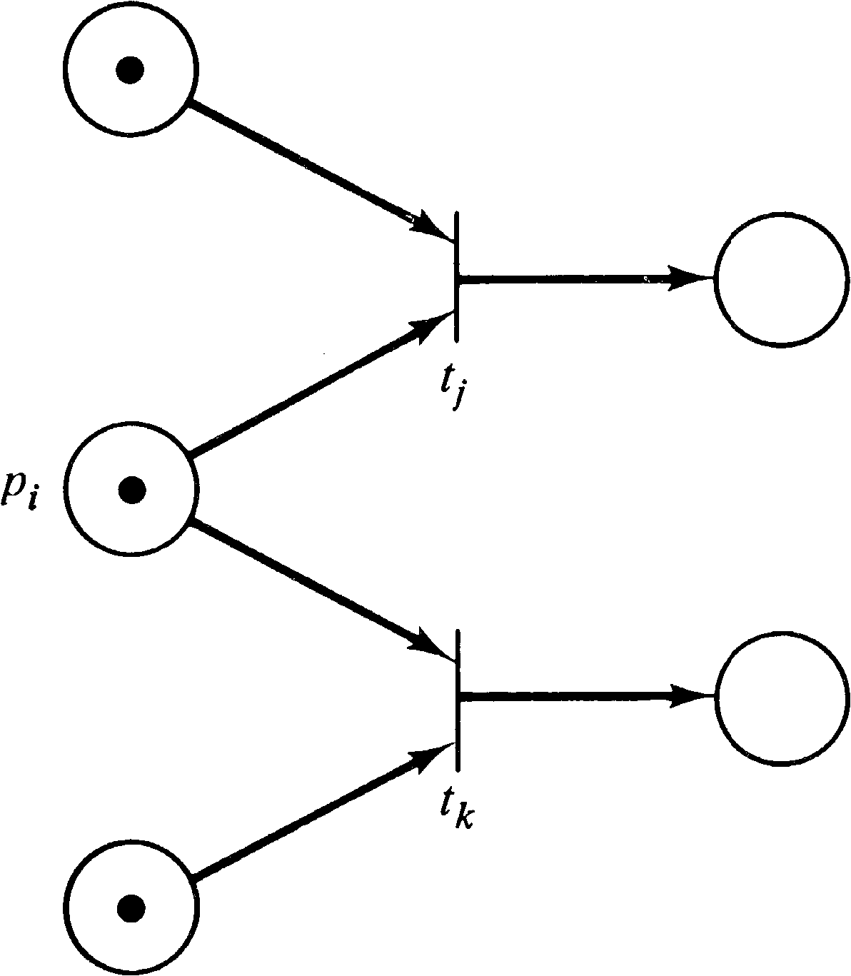
The other situation, where simultaneousness is more
difficult to handle and which may be handled by defining
events to occur nonsimultaneously, is illustrated by Figure
3.8. Here the two enabled transitions are in
conflict. Only one transition can fire, since, in
firing, it removes the token in the shared input and
disables the other transition.
These considerations require that systems to be modeled by
Petri nets be carefully understood in order to properly
model the system behavior. Unfortunately most of the work on
Petri nets has been in the investigation of the properties
of a given net or class of nets. Little explicit attention
has been paid to developing modeling techniques specifically
for Petri nets. However, there are certain areas in which
Petri nets would seem to be the perfect tool for modeling:
those areas in which events occur asynchronously and
independently. To give an understanding of Petri net
modeling, we show in this chapter how Petri nets can be used
to model computer hardware, computer software, and other
systems.
3.3. Computer Hardware
Computer hardware can be thought of at several levels, and
Petri nets can model each of these levels. At one level,
computers are constructed of simple memory devices and
gates; at a higher level, functional units and registers are
used as the fundamental components of the system. At still a
higher level, entire computer systems may be the components
in a multicomputer network. One of the powerful features
of Petri nets is their ability to model each of these
levels. We demonstrate this power by a short discussion and
some examples.
3.3.1. Finite State Machines
At the lowest level, computer systems can be described as state machines. A state machine is a five-tuple ( Q, Σ, Δ, δ, Γ ) where
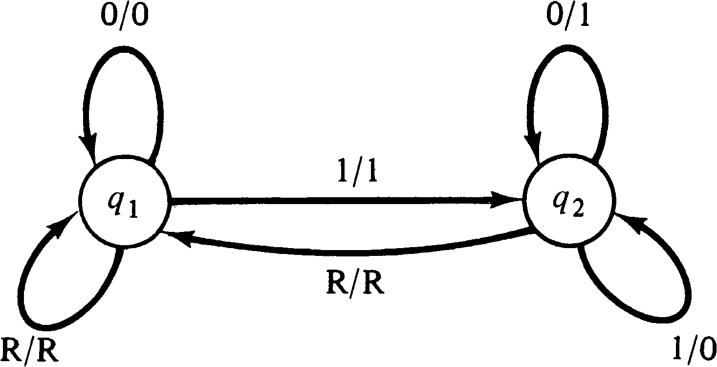
For example, consider the state machine of Figure 3.9. This state machine converts a binary number presented serially low-order bit first to its two's complement negative. Its input alphabet and output alphabet consist of three symbols: 0, 1, and R. The machine starts in state q1. The reset symbol ( R ) signals the end (or beginning) of a number and resets the machine to its initial state. The output of the machine for the reset symbol is simply an echo of the reset symbol.
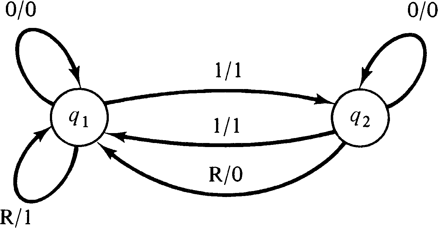
A similar state machine is diagrammed in Figure 3.10. Under
the same inputs, this state machine computes the parity of
the input number. The machine starts in state q1.
The output merely copies the input until the input symbol is
a reset symbol. The output for the reset symbol is 0 for a
number with odd parity and 1 for a number with even parity.
Representing a finite state machine as a Petri net requires
a little thought since there has been no mention of
communication between Petri nets and the outside world.
Petri nets are generally studied in isolation. Modeling
interactions with the outside world can be done in many
ways. For the current problem, we model this
interaction with a special set of places. Each input symbol
will be represented by a place, and each output symbol will
also be represented by a place. We assume that the outside
world will deposit a token in the place corresponding to an
input symbol and then wait for a token to appear in a place
corresponding to an output symbol which will then be removed. This
sequence will then repeat as long as desired. Figure 3.11
illustrates the general scheme.
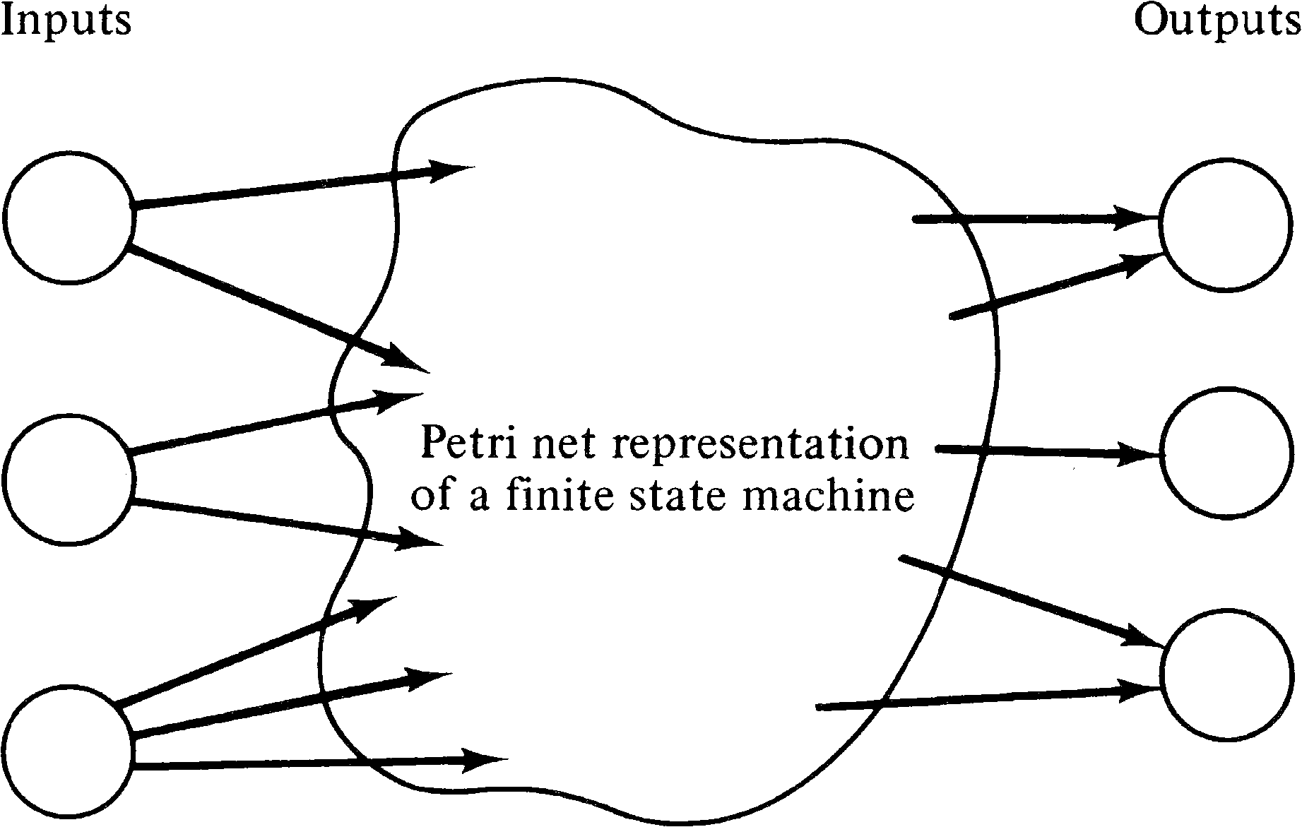
Note that there is a potential for notational confusion here since the places associated with the input symbols and output symbols could reasonably be called input places and output places of the net. This should not be confused with the input places of a transition or output places of a transition, however. Despite this potential confusion, the terms are the most natural ones for both concepts.
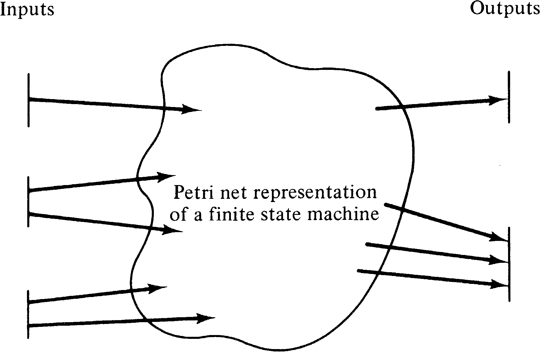
An alternative approach to modeling the inputs and outputs
of the net would be to use transitions. To
indicate the next input symbol, the outside world would
select an input transition and fire it. The Petri net would
respond by (eventually) firing the appropriate one of a set
of output transitions corresponding to the appropriate
output. The outside world would then fire the next input
transition, and so on. This is illustrated in Figure 3.12.
These two approaches can easily be shown to be equivalent,
so we use the first approach, with places modeling
input and output symbols.
Given the place representation of input and output symbols, we can complete the modeling of finite state systems. We represent each state of the state machine by a place in the Petri net. The current state is marked by a token; all other places are empty. Now transitions can be defined to change state and define outputs as follows. For each pair of state and input symbol, we define a transition whose input places are the places corresponding to the state and input symbol and whose output places are the places corresponding to the next state and the output.
For a finite state machine
( Q, Σ, Δ, δ, Γ )
we define a Petri net (P, T, I, O) by
| P | = | Q ∪ Σ ∪ Δ |
| T | = | { tq, σ | q ∈ Q and σ ∈ Σ } |
| I(tq, σ) | = | { q, σ } |
| O(tq, σ) | = | { δ(q, σ), Γ(q, σ) } |
Figure 3.13 is the Petri net corresponding to the state
machine of Figure 3.9. Figure 3.14 is the Petri net
corresponding to Figure 3.10.
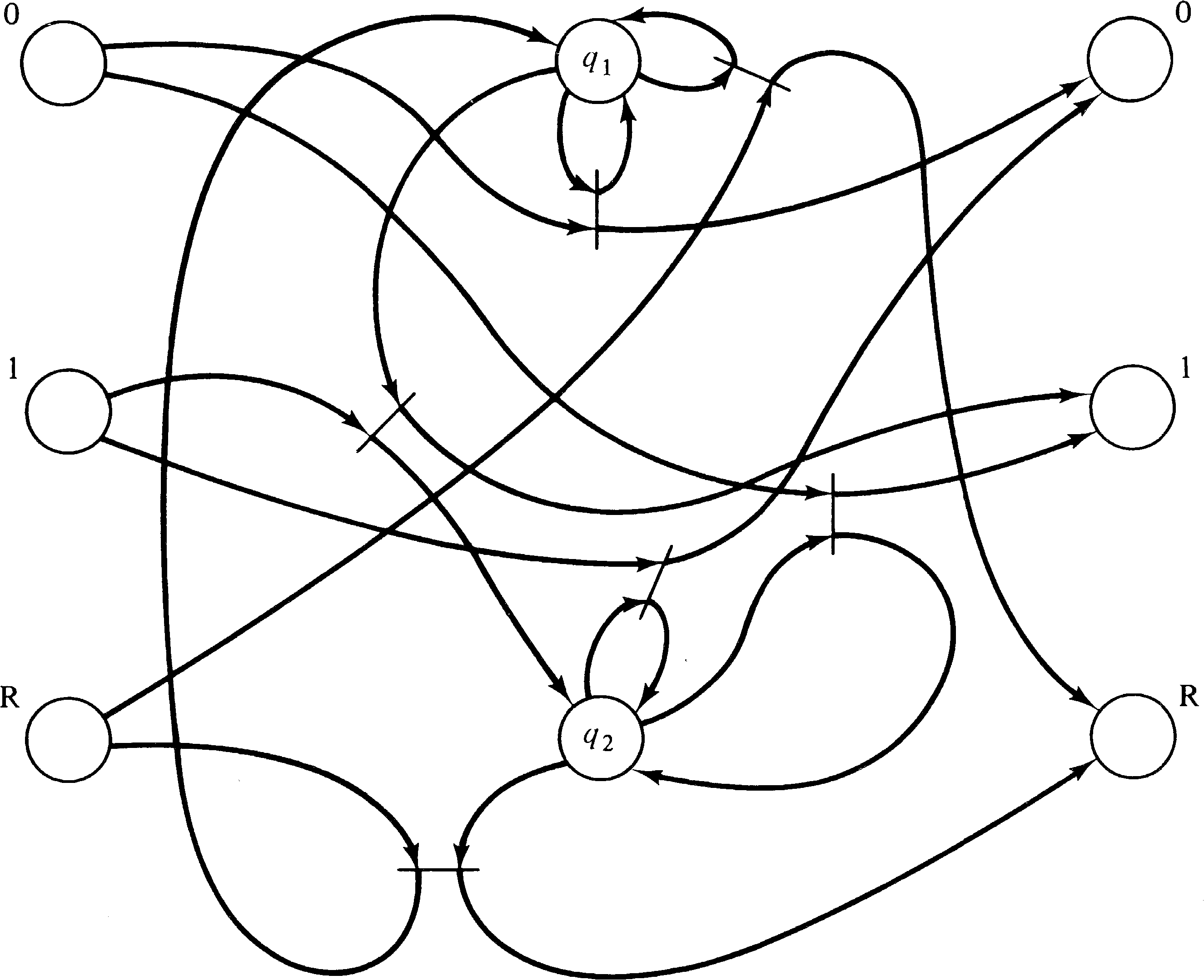
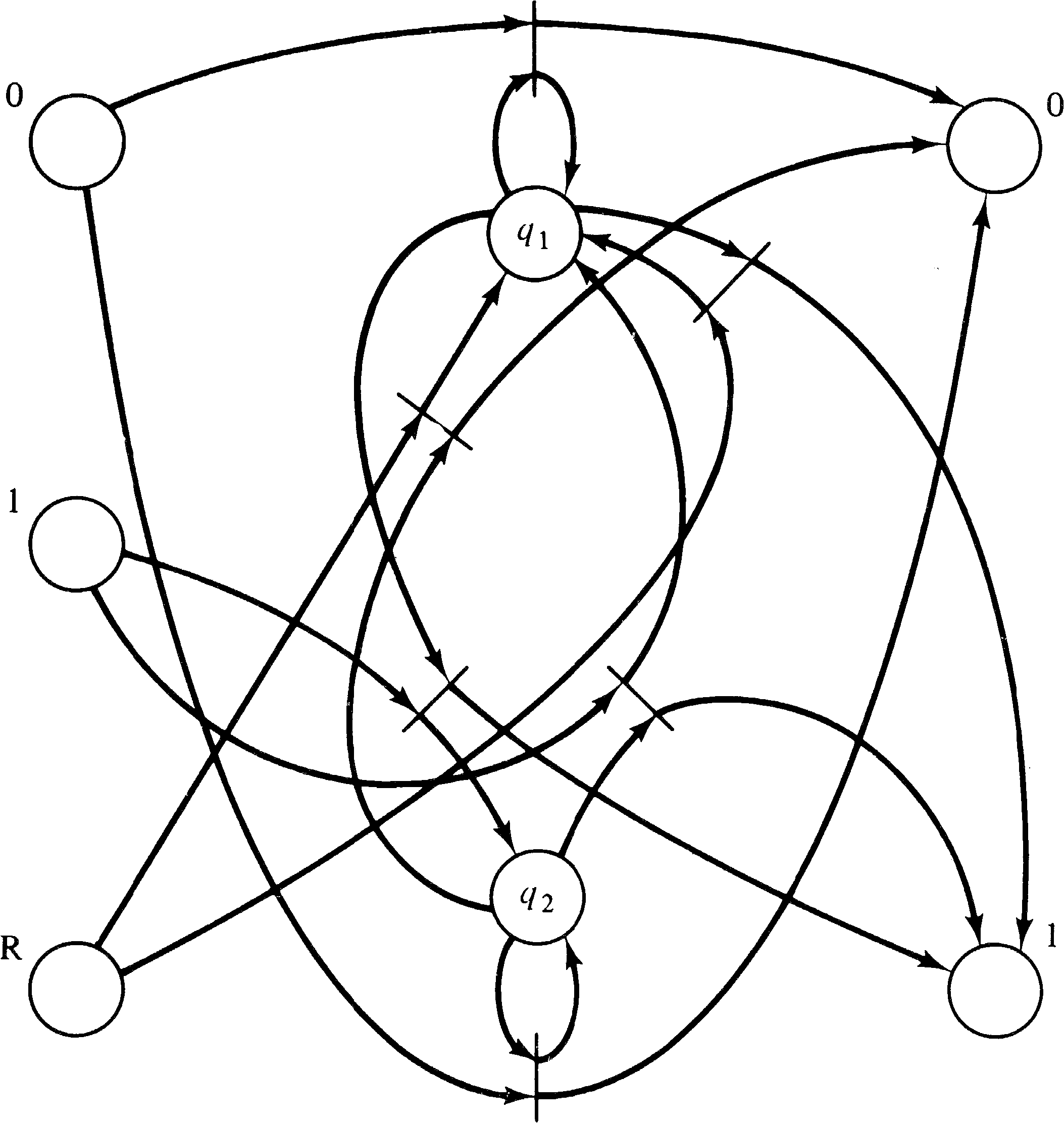
Comparing the Petri nets of Figures 3.13 and 3.14 with the equivalent state machines of Figures 3.9 and 3.10, several questions come to mind. The first is, Why would the Petri net model be preferable to the finite state machine description? The state machine description is more understandable than the Petri net description with its 6 transitions, 24 arcs and 7 or 8 places. This is admitted. However, we have shown that Petri nets can represent any system which can be represented by a state machine, thus demonstrating the power of the Petri net model.
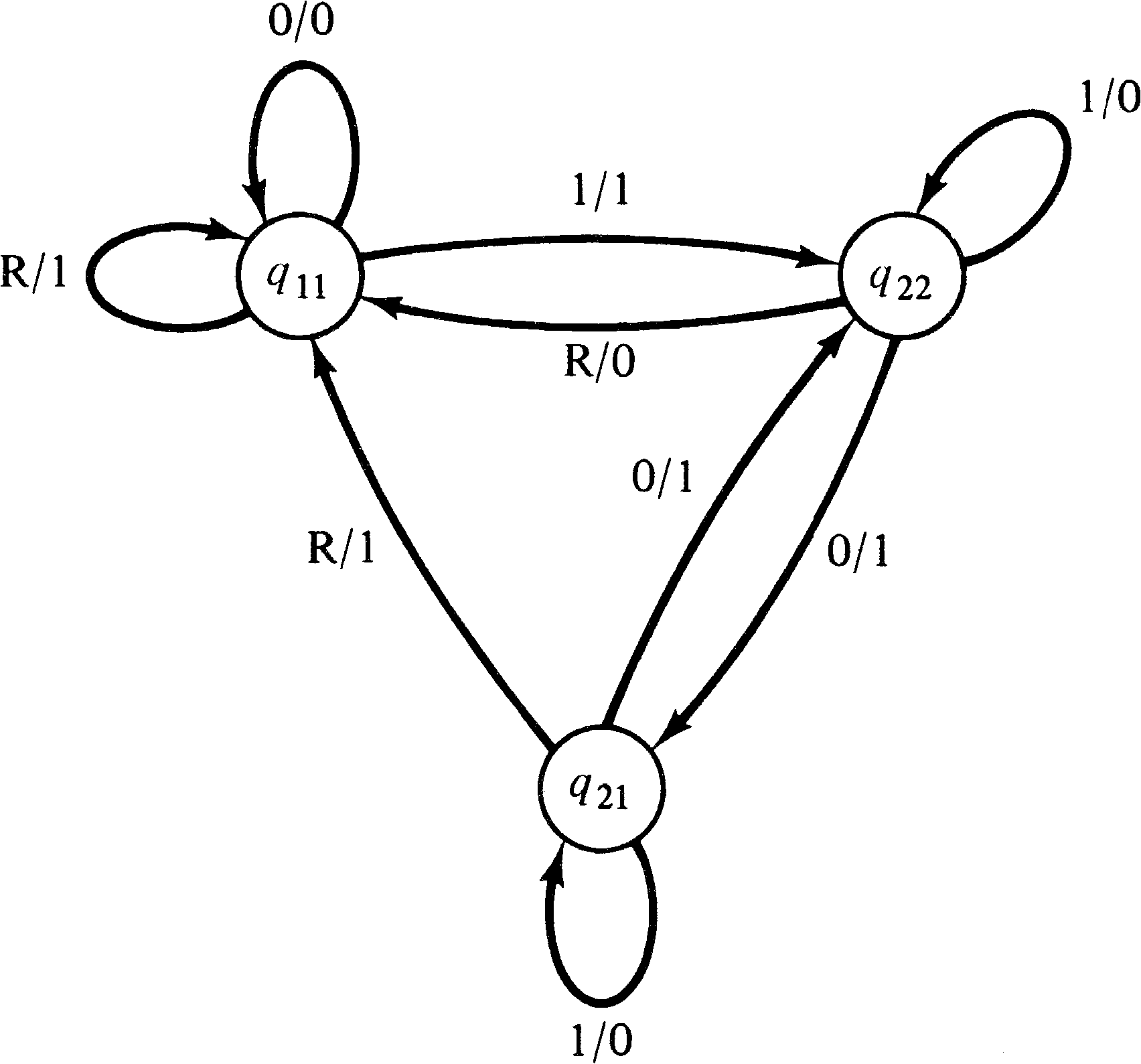
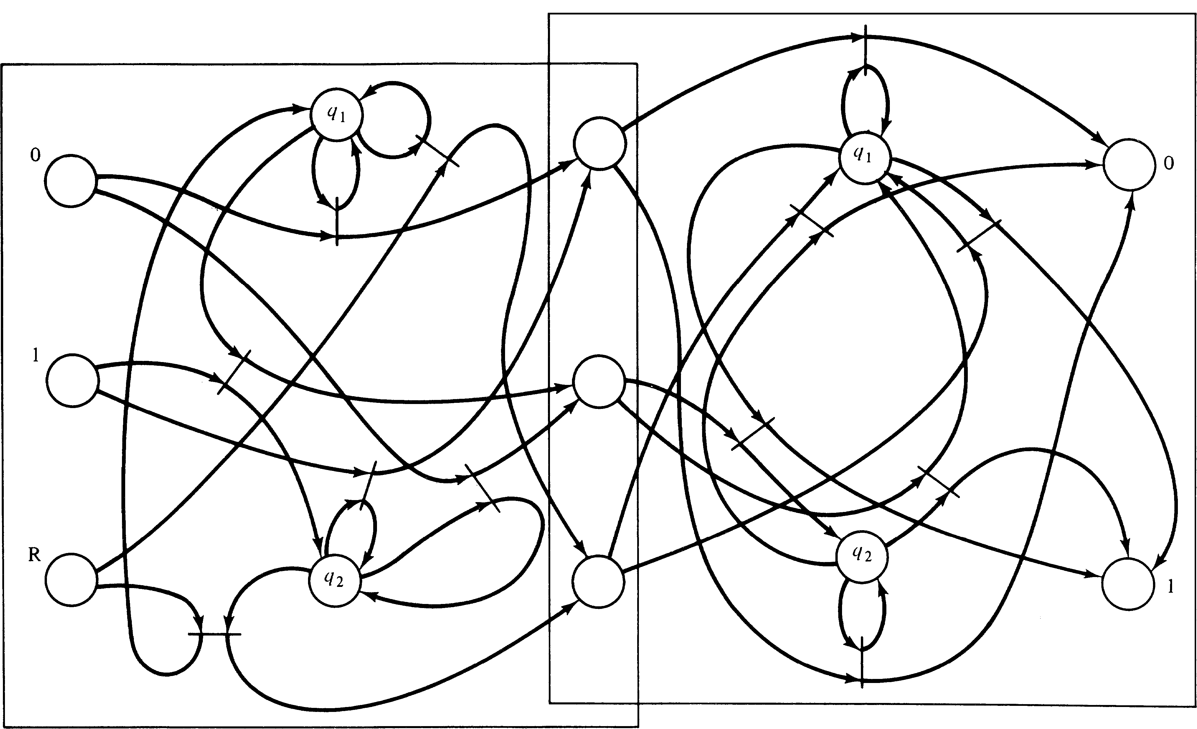
In addition the Petri net model has certain advantages in
the combination of machines. For example, note that the
output alphabet of the machine of Figure 3.13 is identical
to the input alphabet of Figure 3.14. By running the output
of Figure 3.13 into the input of Figure 3.14, we can
construct a composite machine which computes the two's
complement negative and its parity. This combination in a
state machine is complex, requiring a composite state with
components of both submachines, a cross-product
machine. For a Petri net machine, on the other hand, the
composition is simply the overlapping of the output places
of the first net with the input places of the second net.
Figure 3.15 shows the cross-product machine, while Figure
3.16 shows the composite Petri net machine.
Another advantage of the Petri net representation is with
other forms of composition. For example, a parallel
composition allows the component machines to execute
simultaneously. For a state machine, this again involves a
cross-product machine, while for a Petri net, it involves
simply duplicating the input tokens which represent the
input symbols, feeding these into each component Petri net
machine. Finally, on output we simply select the
appropriate output places. For example, if we wish to
combine the two Petri net machines of Figures 3.13 and 3.14
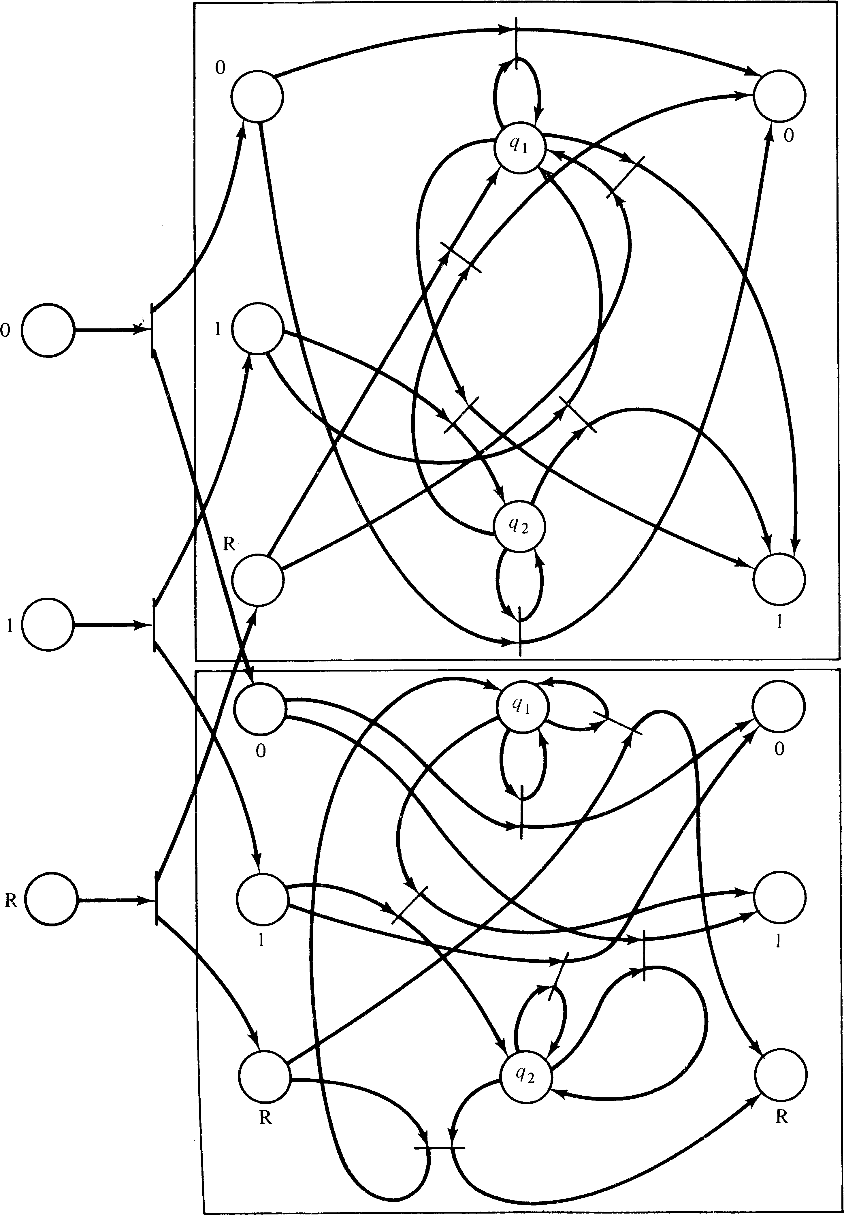
in parallel, this would result in a Petri net like Figure
3.17, which computes the two's complement negative of a
number and its parity. The parity is output when the reset
symbol is input.
The ability to model parallelism and to easily combine subsystems modeled as Petri nets makes the Petri net model very useful for modeling more complex computer hardware. Computer systems are constructed of many components, and many designs attempt to increase throughput by executing several functions in parallel. This makes the Petri net a particularly appropriate representation of the system.
An example of this approach to the construction of a high-performance computer is the use of pipelines [Chen 1971]. This technique is similar to the operation of an assembly line and is especially useful for vector and array processing. A pipeline is composed of a number of stages, which may be in execution simultaneously. When stage k finishes, it passes on its results to stage ( k + 1 ) and looks to stage ( k − 1 ) for new work. If each stage takes t time units and there are n stages, then the complete operation for one operand takes n ⋅ t time units. However, if the pipeline is kept supplied with new operands, it can turn out results at the rate of one every t time units.
As an example, consider the addition of two floating point numbers. The gross steps involved are
The coordination of the different units can be handled in several ways. Typically, the pipeline control is synchronous; the time allowed for each step of the pipe is a fixed constant time t. Every t time units, the result of each unit is shifted down the pipeline to become the input for the next unit. The synchronous approach can unnecessarily hold up processing, however, since the time needed may vary from unit to unit and may also vary within a given unit for different inputs. For example, the postnormalization step in the floating point addition above may take different amounts of time depending on how long the normalization shift should be and whether it should be to the left or to the right. In this case, since the time t must be selected as the maximum time which could be needed by the slowest unit of the pipeline, it could well be the case that all units sit idle most of the time waiting for the remainder of the t time units.
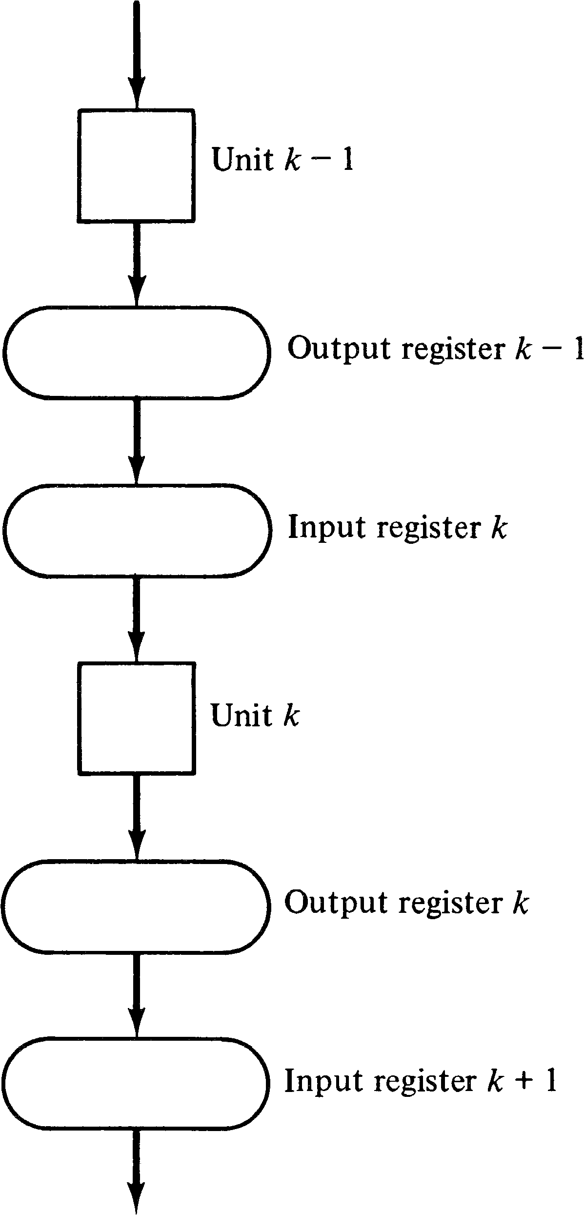
An asynchronous pipeline can speed this up, on average, by signaling when each stage of the pipeline is complete and ready to pass its operand on and receive new operands. The results of stage k of the pipeline can be sent on to stage ( k + 1 ) as soon as stage k is done and stage ( k + 1 ) is free. Consider an arbitrary stage in the pipeline. Obviously, there must be a place to put the inputs and outputs while they are being used or produced. Typically, this involves registers: the unit uses the values in its input (buffer) register to produce values in its output (buffer) register. It must then wait until (1) its output register has been emptied by being copied into the input register of the next stage, and (2) a new input is available in its input register. Thus, the control for stage k of the pipeline needs to know when the following conditions hold:
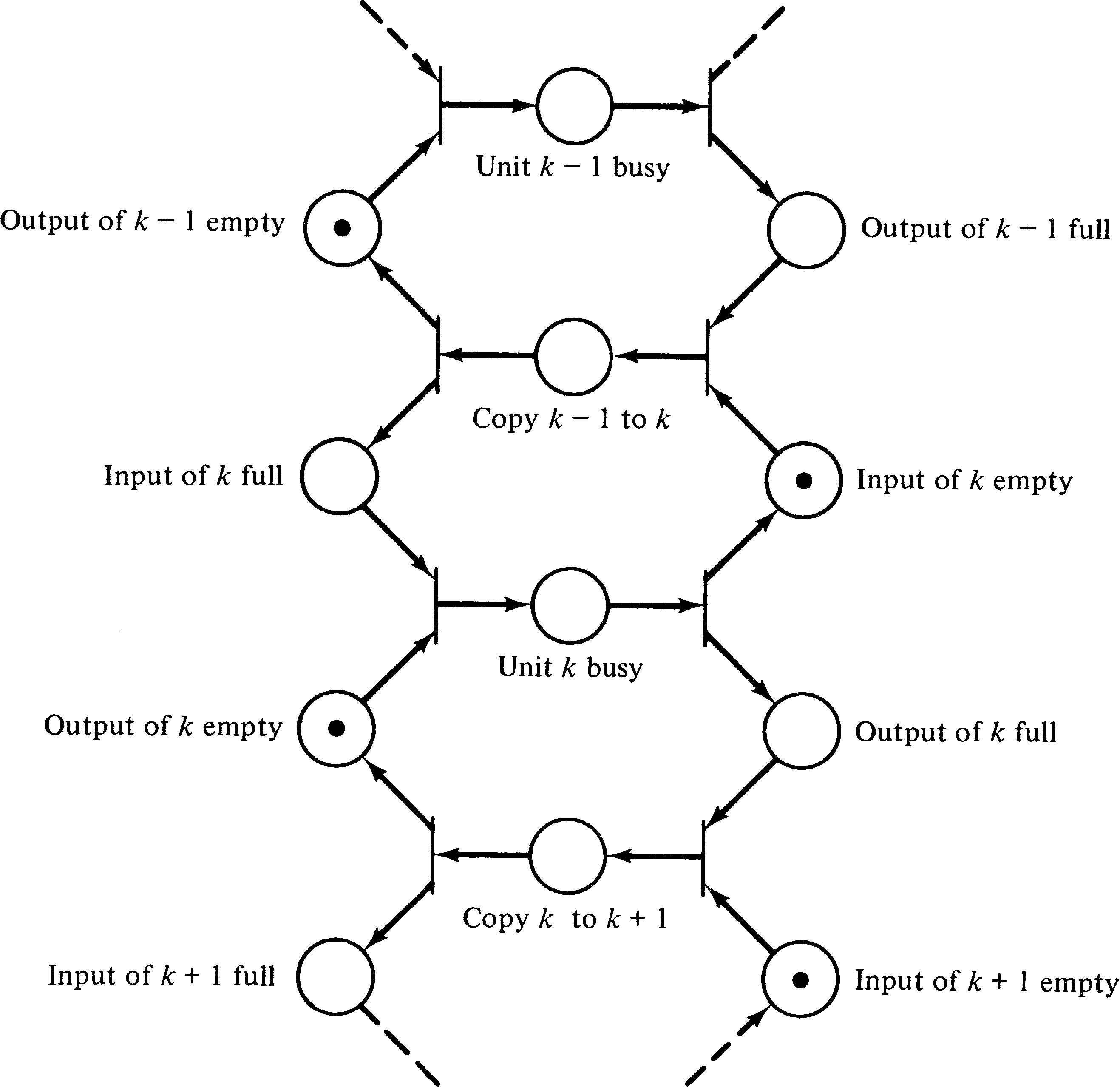
Notice that in this model we have modeled the actual
execution of the units of the pipeline as nonprimitive
events. This allows us to ignore, at this level, the
specific details of what each unit does and concentrate on
their proper interaction. Each operation could also be
modeled as a Petri net. The Petri nets for each unit could
then be substituted into the Petri net of Figure 3.19 to
obtain a more detailed Petri net. This ability to model a
system at several different levels of abstraction, in a
hierarchical manner, can be very useful.
3.3.3. Multiple Functional Units
The pipelined control structure of the previous section is one approach used to build very large fast computer systems. Another approach, used in the CDC 6600 [Thornton 1970] and IBM 360/91 [Anderson et al. 1967], for example, is to provide multiple functional units. On the 6600, 10 functional units are available: 1 branch unit (for conditional jumps), 1 boolean unit (for Boolean operations), 1 shift unit, 1 floating point add unit, 1 fixed point add unit, 2 multiply units, 1 divide unit, and 2 increment units (for indexing). In addition multiple registers are provided to hold the inputs and outputs of the registers. The control unit of the computer attempts to keep several of the independent units in operation simultaneously.
For example, consider the following sequence of instructions based on the CDC 6600 computer system.
The introduction of this type of parallelism, executing several instructions of a program simultaneously, must be controlled so that the results of executing the program with and without parallelism are the same. Certain instructions in the program will require that the results of previous instructions have been successfully computed before the following instructions can proceed. A system which introduces parallelism into a sequential program in such a way as to maintain correct results is determinate. The conditions for maintaining determinacy have been considered by Bernstein [1966]. They are the following: For two operations a and b such that a precedes b in the linear precedence of the program, b can be started before a is done if and only if b does not need the results of a as inputs and the results of b do not change either the inputs or results of a.
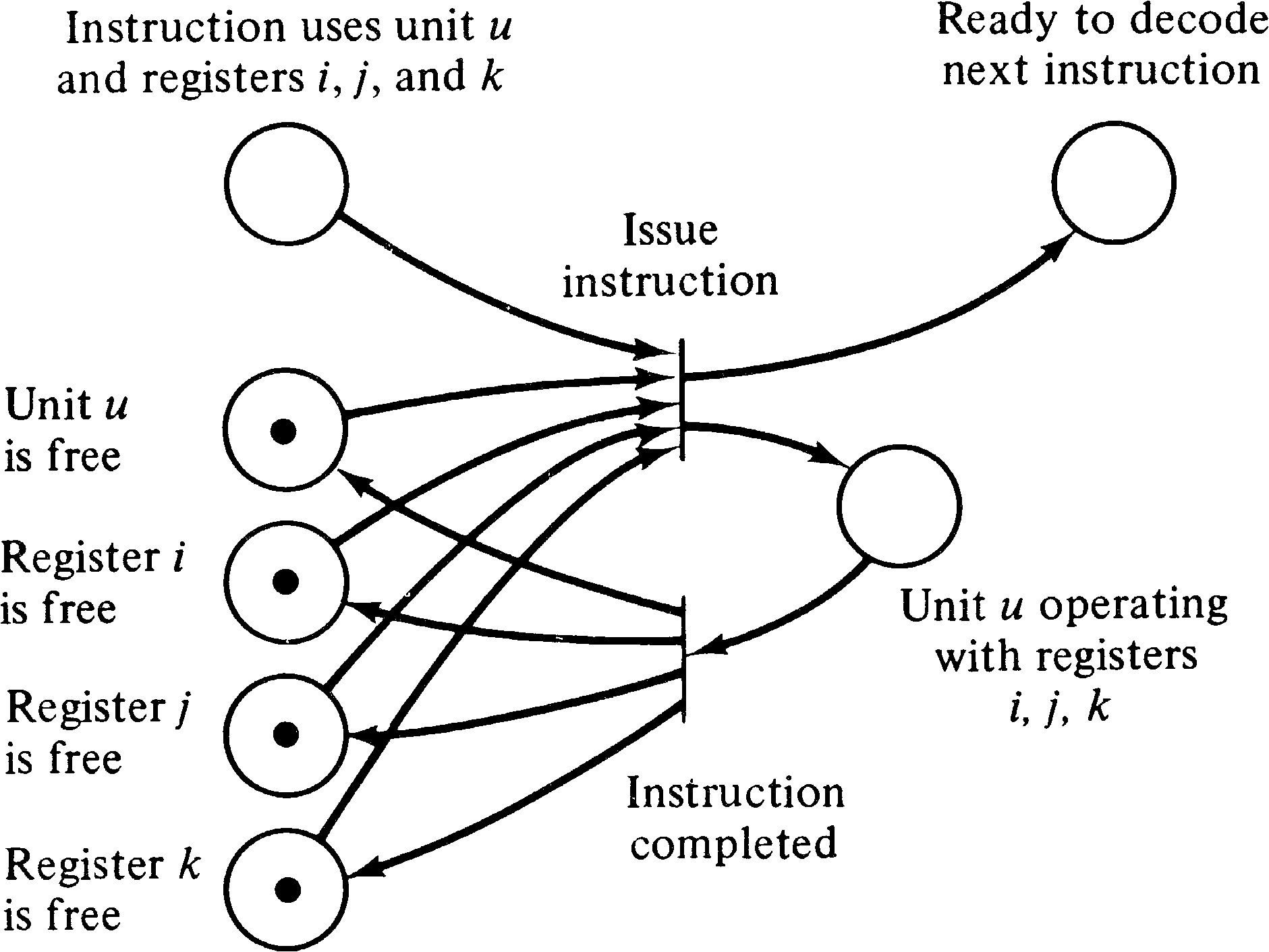
One method of applying these constraints to the construction of a control unit that is to issue instructions to separate functional units is to use a reservation table. An instruction for functional unit u using registers i, j, and k can be issued only if all four of these components are not reserved; when the instruction is issued, all four of them become reserved. If the instruction cannot be issued at this time because either the functional unit or one of the registers is in use, the control unit waits until the instruction can be issued before continuing on to the next instruction.
This sort of scheme can be modeled as a Petri net. To each
functional unit and each register, we associate a place. If
the unit or register is free, a token will be in the place; if
it is not, no token will be in the place. Multiple
identical functional units can be indicated by multiple
tokens in the places. Figure 3.20 shows a portion of a
Petri net which could be used to model the execution of an
instruction using unit u and registers
i, j, and k. Modeling the entire control unit would
of course require a much larger Petri net.
The scheme described above is a very simple method of introducing parallelism and does not consider, for example, the fact that multiple functional units can use the same register as an input simultaneously. Thus, this scheme may not produce schedules with maximal parallelism [Keller 1975b]. However, there are other schemes which can do so. These (more complicated) schemes can also be modeled by (more complicated) Petri nets. These nets may be very large. Consider that the CDC 6600 has 24 different registers and 64 different instructions. If each instruction and triple of registers needed a place corresponding to “unit u is operating with registers i, j, and k,” then over a half million places and transitions would be needed. The main problem here is the difficulty of modeling the fact that the contents of an internal register may specify which registers and units are to be used (i.e., indexing).
(Any given program will not use all possible combinations of
registers and units, however. This allowed Shapiro and
Saint [1970] to model the 6600 computer system with a Petri
net. This Petri net model was then used to optimize code
generation for a FORTRAN compiler, as we shall see in
Section 3.5.)
3.4. Computer Software
In addition to computer hardware, computer software can be
modeled by Petri nets. This is perhaps the most common use
of Petri nets and has the greatest potential for useful
results. Many systems have been developed over the years
for the description and modeling of computer hardware, but
it is only in the past few years that efforts have been made
to formally model computer software. Much of this recent
effort is still concerned with the analysis, specification
and description of sequential programs; systems of
concurrent processes are still major research topics. In
this section we show how Petri nets can faithfully model
many systems of concurrently executing cooperating
processes.
3.4.1. Flowcharts
The degenerate case of a system of concurrent processes is a system with exactly one process. We first examine how a single process can be represented by a Petri net, and then by combining Petri nets representing several processes we would have a system of concurrent processes.
A single process is described by a program. This program can be written in many languages, but for convenience, let us assume a general-purpose language such as ALGOL, FORTRAN, PL/I, COBOL, Pascal, BASIC, or even assembly language. The program represents two separate aspects of the process: computation and control. Computation is concerned with the actual arithmetic and logical operations, the input and output, and general manipulation of memory locations and their values. Control, on the other hand, is not concerned with the values or computations being performed but only with the order of their performance.
Petri nets can best represent the control structure of programs. Petri nets are meant to model the sequencing of instructions and the flow of information and computation but not the actual information values themselves. A model of a system, by its nature, is an abstraction of the modeled system. As such it ignores the specific details as much as possible. If all the details were modeled, then the model would be a duplicate of the modeled system, not an abstraction.
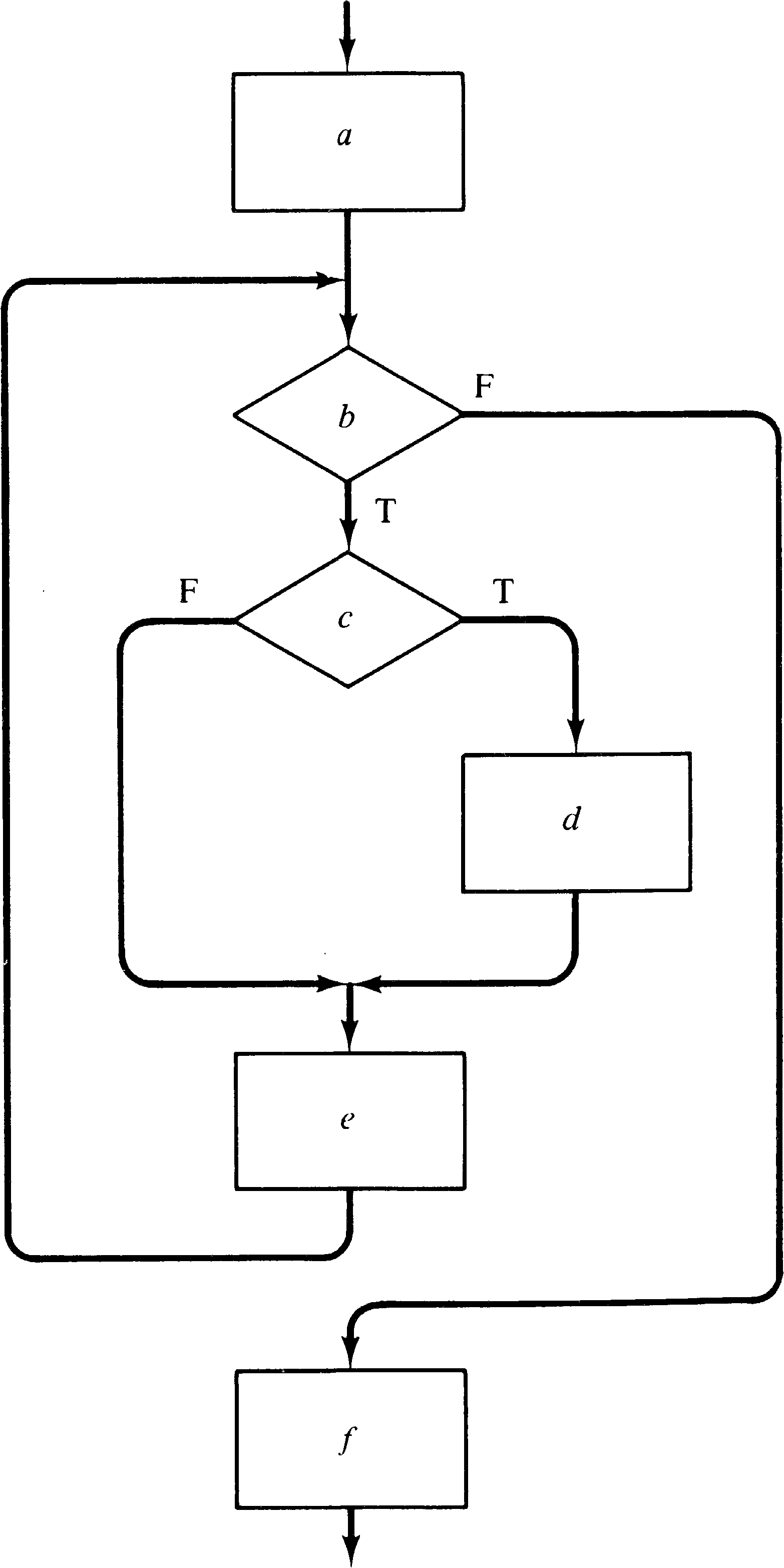
One standard means of representing the control structure of
a program is with a flowchart. A flowchart represents
the flow of control in a program. For example, the program
of Figure 3.21 is represented by the flowchart of Figure
3.22. Notice that the flowchart of Figure 3.22 does not
specify the computations to be done, only the structure of
the program. This flowchart is uninterpreted. Figure
3.23 shows how an interpretation can be applied to the
actions of the flowchart to represent the program of Figure
3.21.
 begin
    Input(y1);
    Input(y2);
    y3 := 1;
    while y1 > 0
       do begin
           if odd(y1)
           then begin
                   y3 := y3 * y2;
                   y1 := y1 − 1;
                end;
            y2 := y2 * y2;
            y1 := y1 − 2;
         end;
    Output(y3);
 end;
| Action | Interpretation |
| a | Input(y1); Input(y2); y3 := 1; |
| b | y1 > 0 ? |
| c | Odd(y1) ? |
| d | y3 := y3 * y2; y1 := y1 - 1; |
| e | y2 := y2 * y2; y1 := y1 / 2; |
| f | Output (y3); |
Every sequential program can be represented by a flowchart. Thus, by showing how a flowchart can be represented by a Petri net, we have shown how to represent an uninterpreted program by a Petri net.
A flowchart would appear to be very similar to a Petri net: A flowchart is composed of nodes (of two types: decisions represented by the diamond shapes and computations represented by the rectangles) and arcs between them. A convenient way to execute a flowchart is to introduce a token which represents the current instruction. As the instructions execute, the token moves around the flowchart. The similarity between these graphical representations of a program and a Petri net would seem to indicate that we can replace the nodes of the flowchart by places and the arcs by transitions to create an equivalent Petri net. This is the approach taken to converting a finite state machine into a Petri net (see Section 3.3.1).
However, consider that in the Petri net model, the
transitions model actions, while in the flowchart model, the
nodes model actions. Also, if our current-instruction token
in a flowchart were to want to “rest,” it would pause
between nodes, on an arc, not within a box. Thus the
appropriate translation from a flowchart to a Petri net
replaces the nodes of the flowchart with transitions in the
Petri net and the arcs of the flowchart with places in the
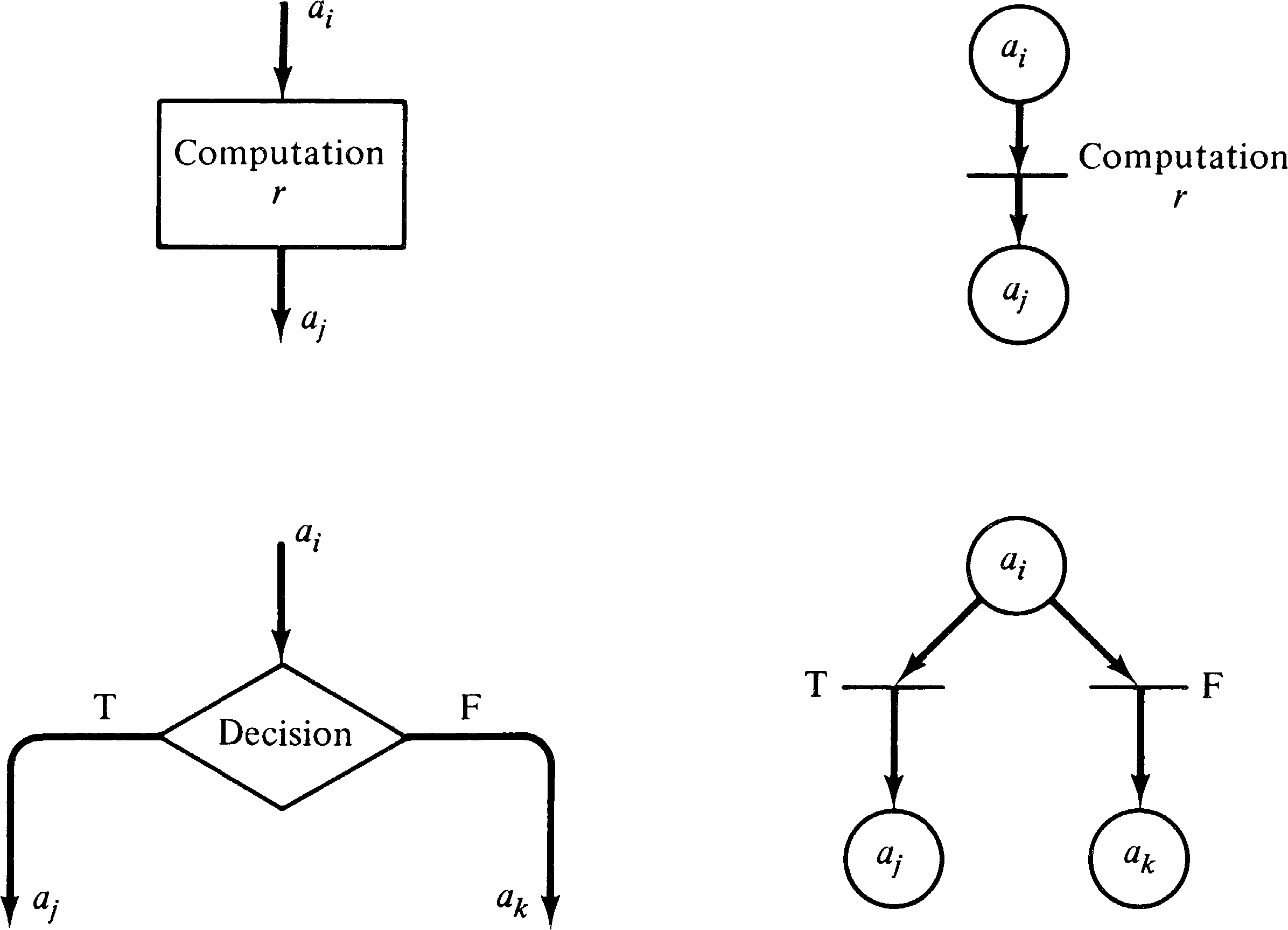
Petri net. Each arc of the flowchart is represented by
exactly one place in the corresponding Petri net. The nodes
of the flowchart are represented in different ways,
depending on the type of the node: computation or
decision. Figure 3.24 illustrates the two methods of
translation. Figure 3.25 applies this translation to the
flowchart of Figure 3.22 to produce an equivalent Petri net.
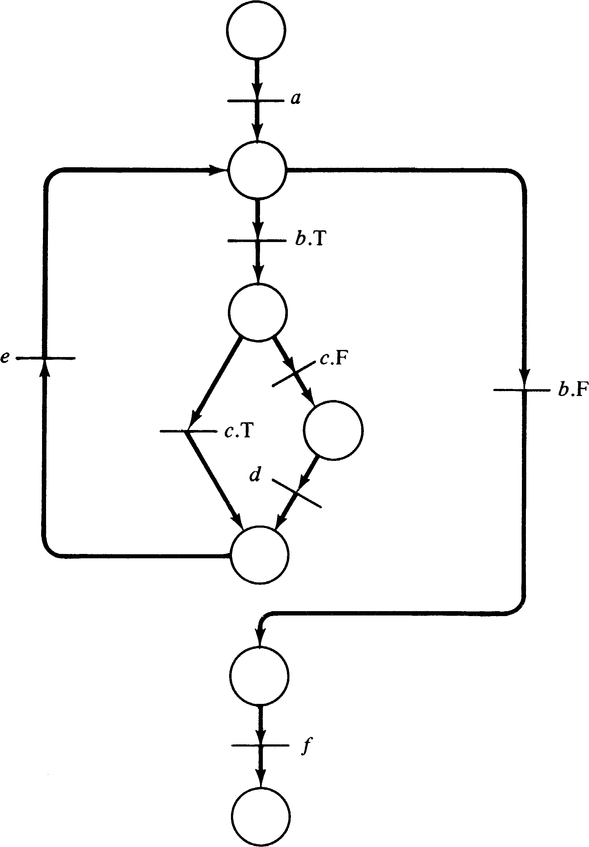
A point or two to notice about the Petri net of Figure 3.25 concerns the meaning of the Petri net components. What is the meaning of the places? The easiest answer is to consider the program counter interpretation of the flowchart token. In this sense, a token residing in a place means that the program counter is positioned ready to execute the next instruction. Every place has a unique output transition, except for places which precede decisions; these places have two output transitions corresponding to true and false outcomes of the decision predicate.
The transitions are obviously associated with the actions of
the program: the computations and the decisions. If we wish
to interpret the Petri net, we must provide an
interpretation for each transition. Notice also that
transitions for computational actions have a unique input
and unique output, and that no conflict can exist for a
transition representing a computation, since its input place
is not an input place for any other transition. Decision
actions do introduce conflict into the net, but in a very
constrained way: either choice can be freely made. This
choice can either be made nondeterministically
(i.e., randomly) or may be controlled by some
external force (i.e., by an agent which computes
the truth or falsity of the decision and forces the correct
transition to fire). The distinction between these two
interpretations of conflict resolution is a matter of
philosophy.
3.4.2. Parallelism
Parallelism or concurrency can now be introduced in several ways. Consider the case of two concurrent processes. Each process can be represented by a Petri net. Thus the composite Petri net which is simply the union of the Petri nets for each of the two processes can represent the concurrent execution of the two processes. The initial marking of the composite Petri net has two tokens, one in each place representing the initial program counter of a process. This introduces a parallelism which cannot be represented in a flowchart, but still not a very useful one.
Another approach is to consider how parallelism would
normally be introduced into a process in a computer system.
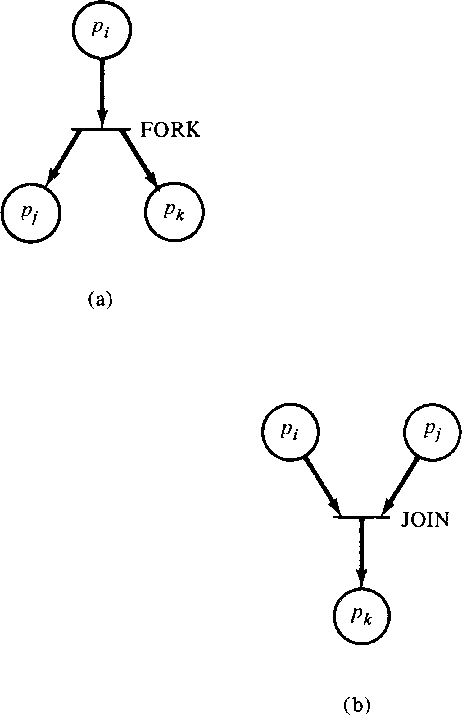
Several proposals have been made. One of the simplest
involves the FORK and JOIN operations originally proposed by
Dennis and Van Horn [1966]. A FORK j operation executed at
location i results in the current process continuing at
location i + 1, and a new process being created with execution
started at location j. A JOIN operation will recombine two
processes into one (or equivalently will destroy one of the
two and let the other proceed). These operations can be
modeled in a Petri net as shown in Figure 3.26.
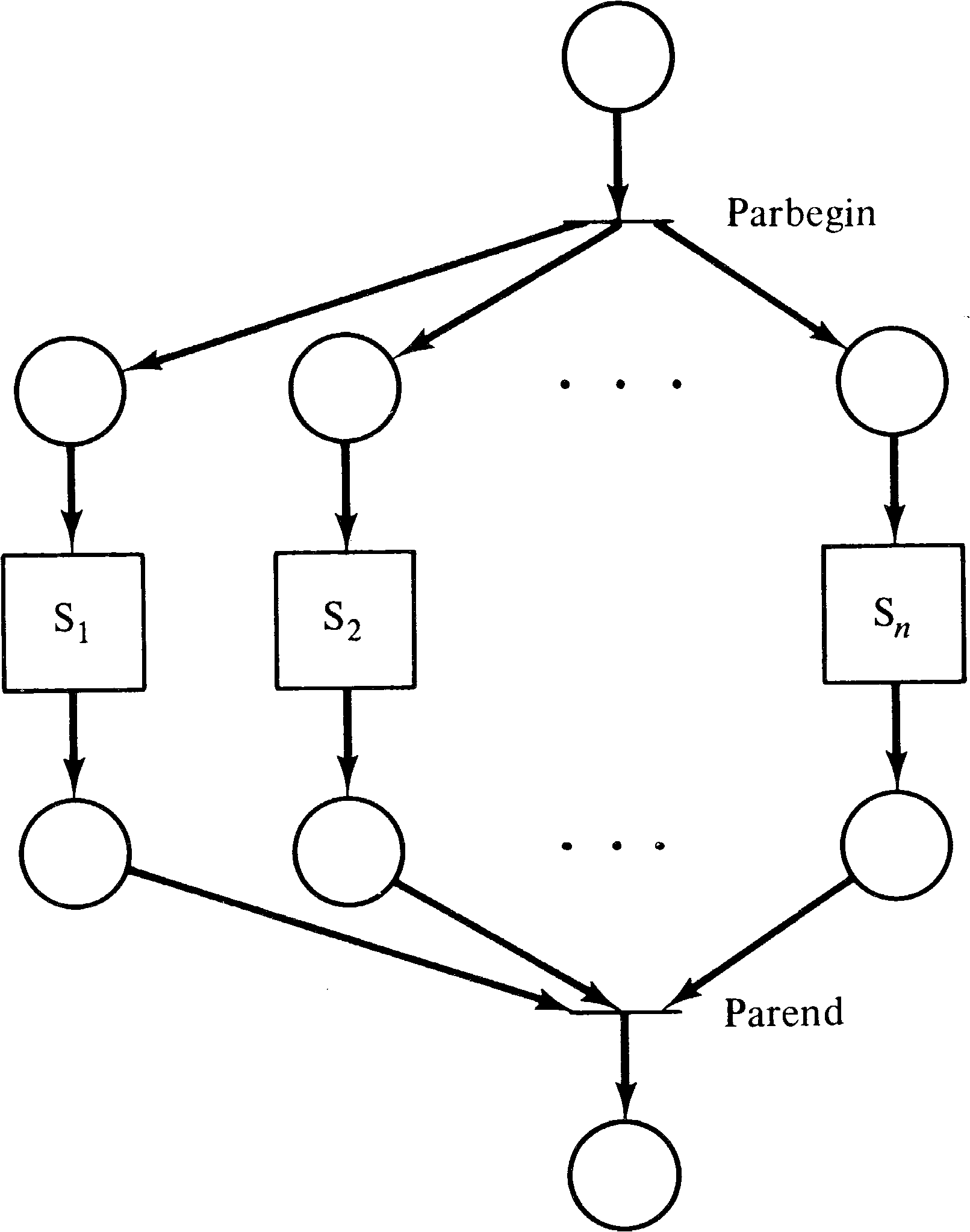
Another suggestion for introducing parallelism is the
parbegin and parend control structure [Dijkstra
1968]. This control structure was suggested by Dijkstra and
is of the general form parbegin S1;
S2; ...; Sn parend, where the Si are
statements. The meaning of the parbegin/parend structure is
to execute each of the statements, S1,
S2, …, Sn in parallel. This construct
can be represented in a Petri net as shown in Figure 3.27.
Parallelism is usefully introduced into the solution of a problem only if the component processes can cooperate in the solution of the problem. Such cooperation requires the sharing of information and resources between the processes. This sharing must be controlled to ensure correct operation of the overall system. A variety of synchronization problems have been proposed in the literature to illustrate the types of problems which can arise between cooperating processes. Among these are the mutual exclusion problem [Dijkstra 1965], the producer/consumer problem [Dijkstra 1968], the dining philosophers problem [Dijkstra 1968], and the readers/writers problem [Courtois et al. 1971].
These problems are classics in the field of synchronization
problems; every new suggestion for a synchronization
mechanism must be able to handle these problems. Although
Petri nets are a modeling scheme, and not a synchronization
mechanism, Petri nets must certainly be able to model
synchronization mechanisms which solve these problems. Thus,
we present here some solutions to these problems, as Petri
nets. This presentation is based in part on the work of
Cooprider [1976].
3.4.4. The Mutual Exclusion Problem
Assume that several processes share a common variable, record, file, or other data item. This shared data item may be used in several ways by the processes but these uses can be grossly classified as needing to either read the value of the data item or write a new value. These two operations are often the only primitive operations. This means that to update the shared data item, a process must first read the old value, then compute the new value, and finally write the new value in place. A problem may occur if two processes attempt to execute this sequence of instructions at the same time. The following sequence may occur.
To prevent these sorts of problems, it is necessary to provide a mechanism for mutual exclusion. Mutual exclusion is a technique of defining entry and exit code so that at most one process is accessing a shared data object at a time. The code which accesses the shared object and needs protection from interference by other processes is called a critical section. The idea is that as a process is about to execute its critical section, it first waits until no other process is executing its own critical section. Then it “locks” access to the critical section, preventing any other process from entering its critical section. It enters the critical section, executes it, and as it leaves the critical section “unlocks” it to allow other processes to access it.
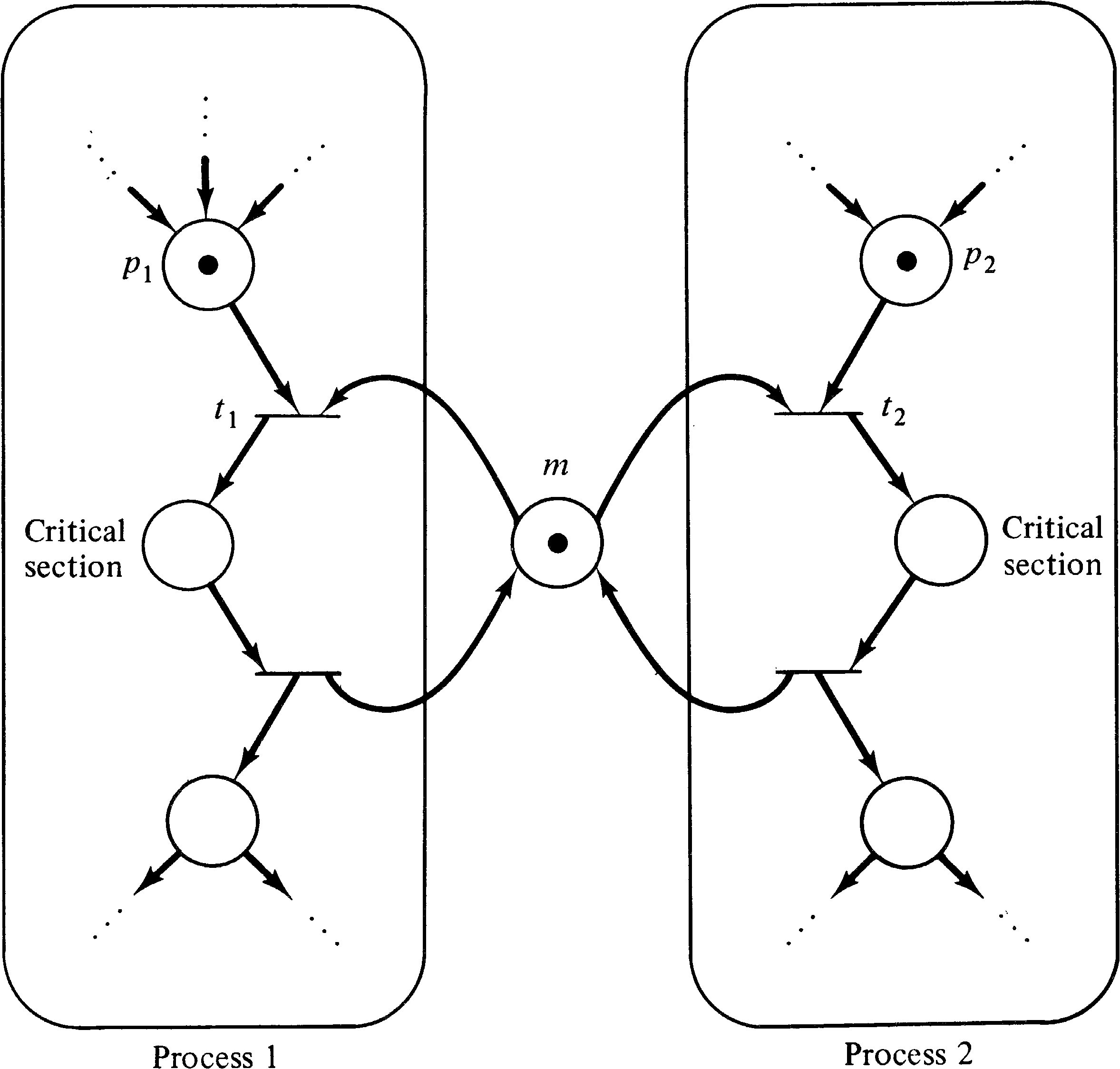
This problem can be solved by a Petri net such as Figure
3.28. The place m represents the permission to enter
the critical section. For a process to enter the
critical section, it must have a token in p1 or
p2, as appropriate, signaling that it wishes to
enter the critical section, and there must be a token
in m signaling permission to enter. If both
processes wish to enter simultaneously, then transitions
t1 and t2 are in conflict, and only one
of them can fire. Firing t1 will disable
transition t2, requiring process 2 to wait until
the first process exits its critical section and puts a
token back in place m.
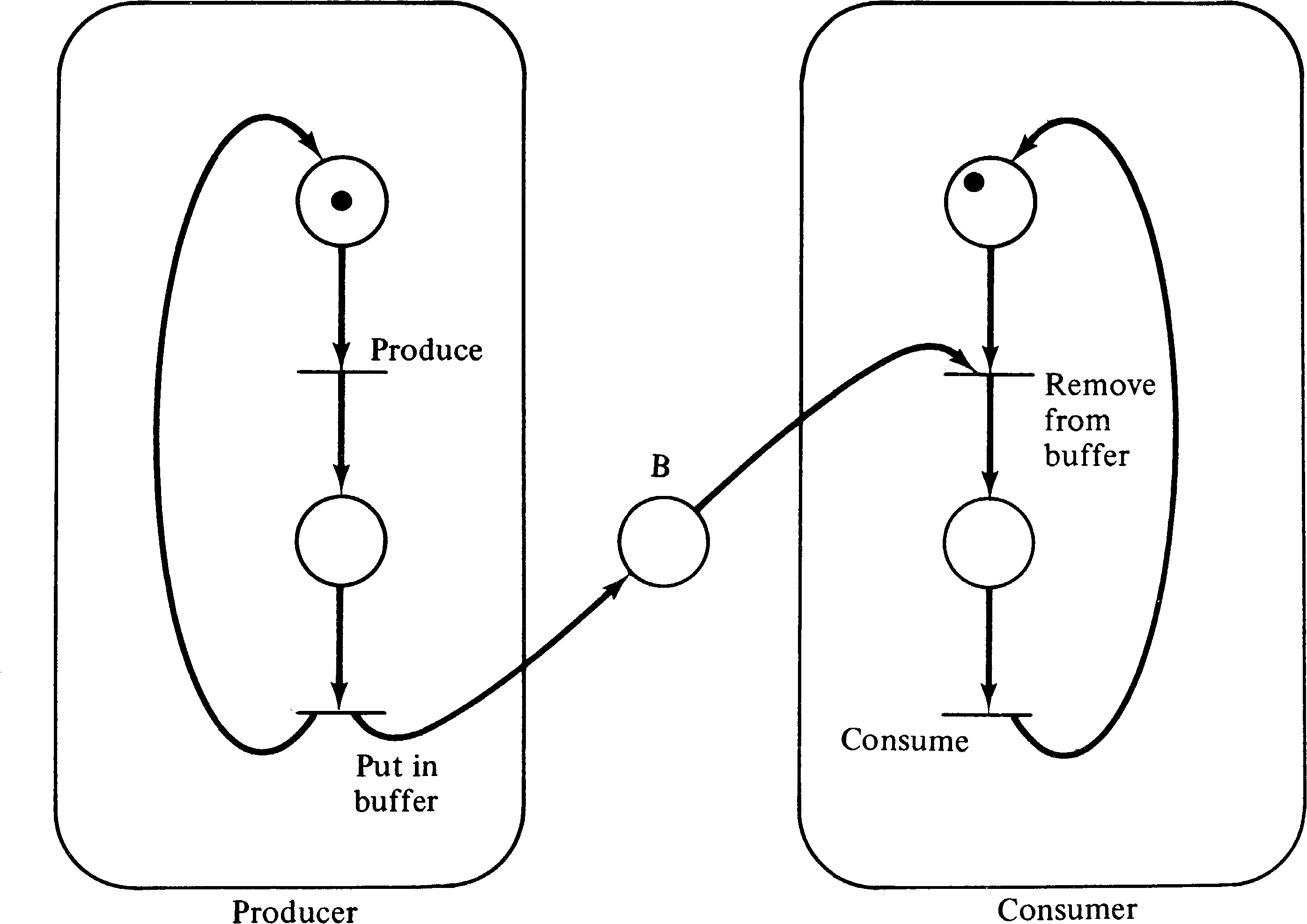
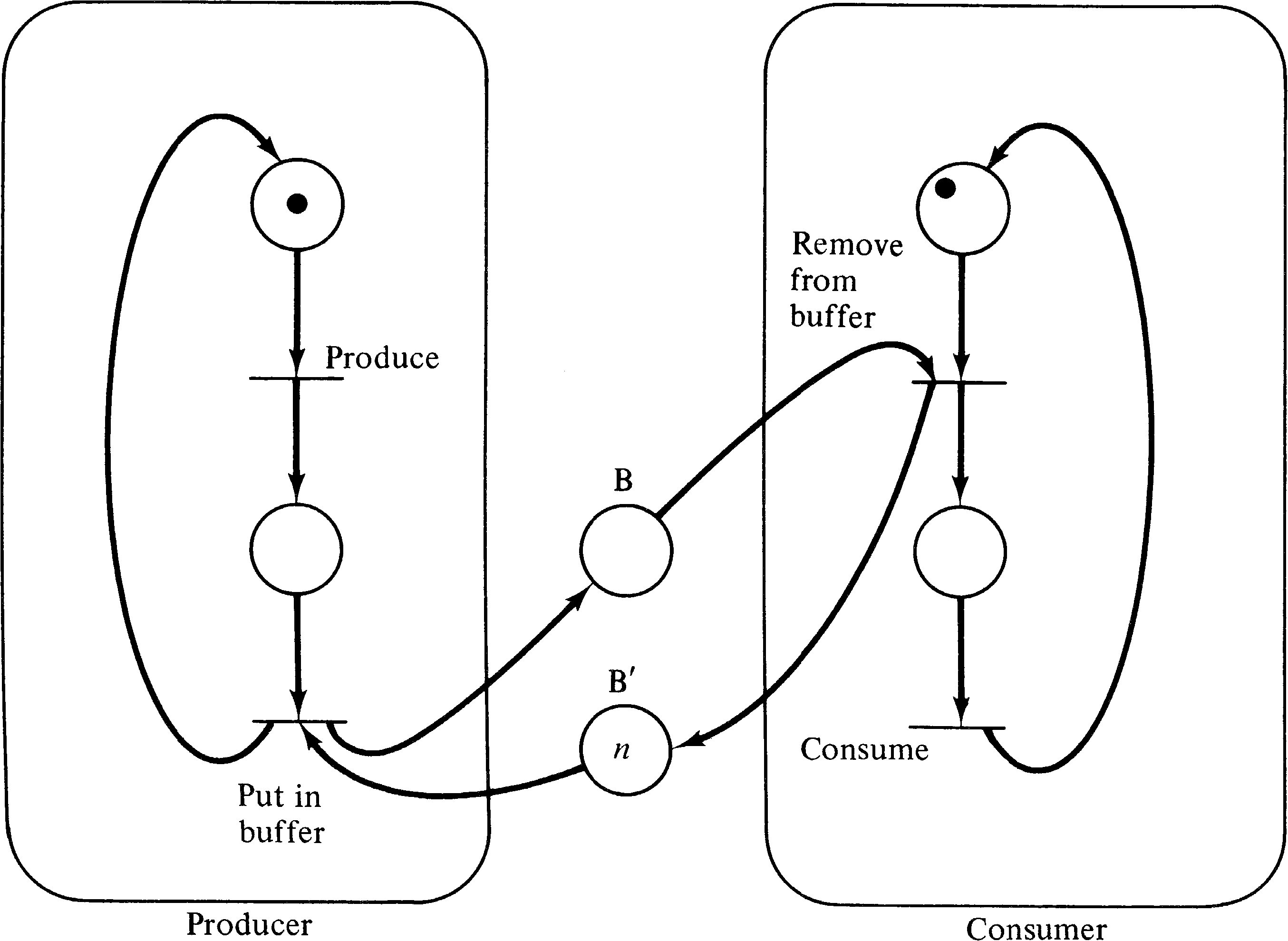
The producer/consumer problem also involves a shared data
object, but in this case the shared object is specified to
be a buffer. The producer process creates objects which are
put in the buffer; the consumer waits until an object has
been put in the buffer, removes it, and consumes it. This
can be modeled as shown in Figure 3.29. The place B
represents the buffer; each token represents an item which
has been produced but not yet consumed.
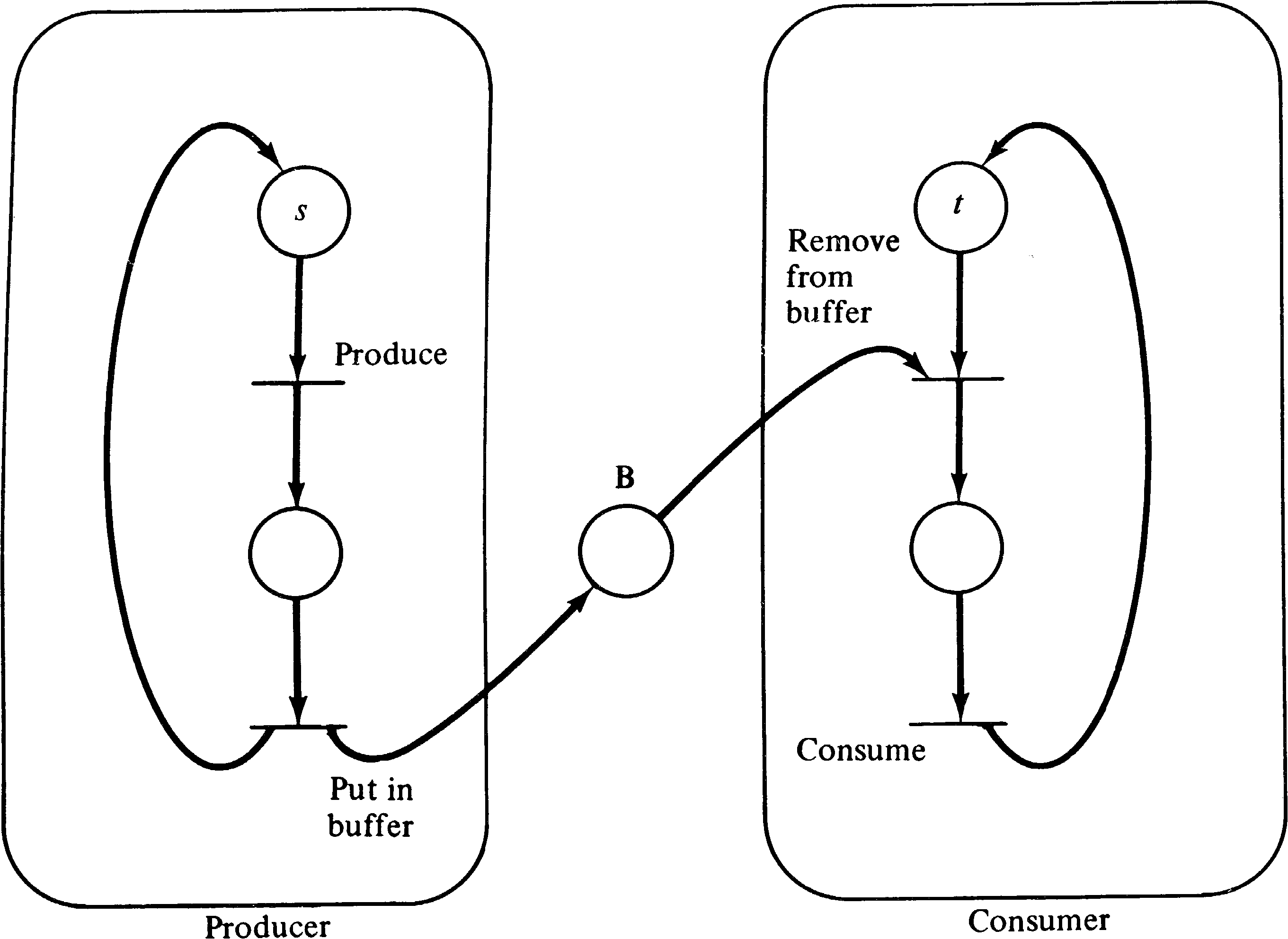
A variant on this problem is the
multiple-producer/multiple-consumer problem. In this
variant, multiple producers produce items which are placed
in a common buffer for the multiple consumers. Figure 3.30
is a Petri net solution to this problem. It is the same as
Figure 3.29, except that to represent s producers and
t consumers, we start the system with s tokens
in the initial place of the producer process and t
tokens in the initial place of the consumer process. This
represents s producers and t consumers executing
reentrant, shared bodies of code. An alternative would be
to duplicate the code for the producer and consumer
processes, but this results in the same behavior with a much
larger net.
Another variant is the bounded buffer producer/consumer
problem. In this version of the producer/consumer problem,
it is recognized that the buffer between the producer and
the consumer is likely to be bounded, that is, have only
n positions for items. Thus the producer cannot
always produce as fast as desired but may have to wait if
the consumer is slow and the buffer has filled. Figure 3.31
is a solution to this problem. The bounded buffer is
represented by two places: B represents the number of items
which have been produced but not yet consumed (the number of
full positions); B′ represents the number of empty
positions in the buffer. Originally B′ has
n tokens and B has zero. If the buffer gets full, then
B′ will have zero tokens and B will have n. At this
point if the producer tries to put another item in the
buffer, it will be stopped because there is no token in
B′ to enable that transition.
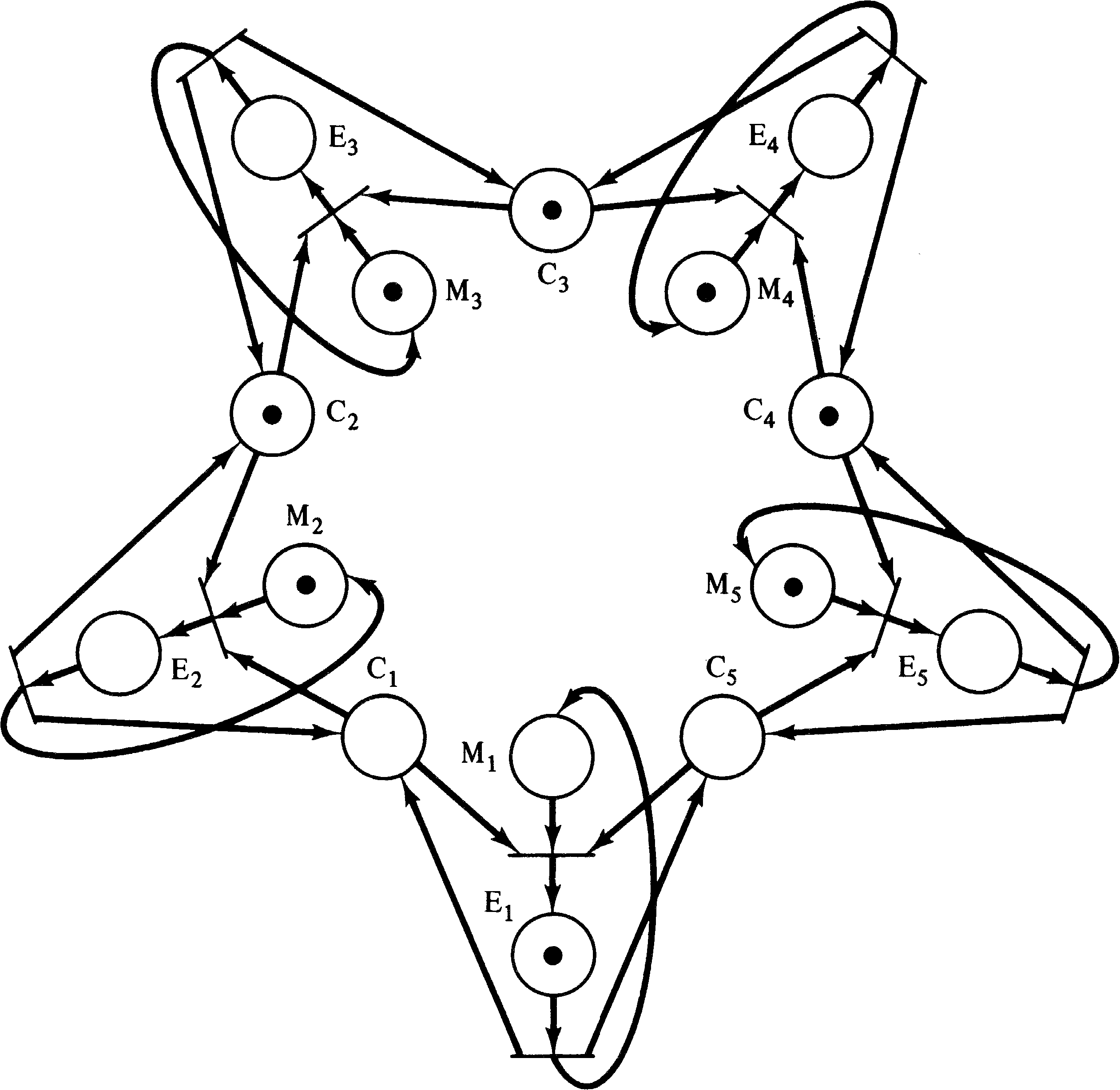
The dining philosophers problem was suggested by Dijkstra [1968] and concerns five philosophers who alternatively think and eat. The philosophers are seated at a large round table on which are a large number of Chinese foods. Between each philosopher is one chopstick. However, to eat Chinese food, you need two chopsticks; hence each philosopher must pick up both the chopstick on the left and the chopstick on the right. The problem, of course, is that if all philosophers pick up the chopstick on their left and then wait for the chopstick to their right, they will all wait forever and starve (a deadlock condition).
Figure 3.32 illustrates the Petri net solution to this
problem. The places C1, …, C5 represent the
chopsticks, and since each is initially free, a token resides
in each in the initial marking. Each philosopher is
represented by two places Mi and Ei
representing the meditating and eating states, respectively.
For a philosopher to move from the meditating state
to the eating state, both chopsticks (the one to the left
and the one to the right) must be available. This is easily
modeled in the Petri net.
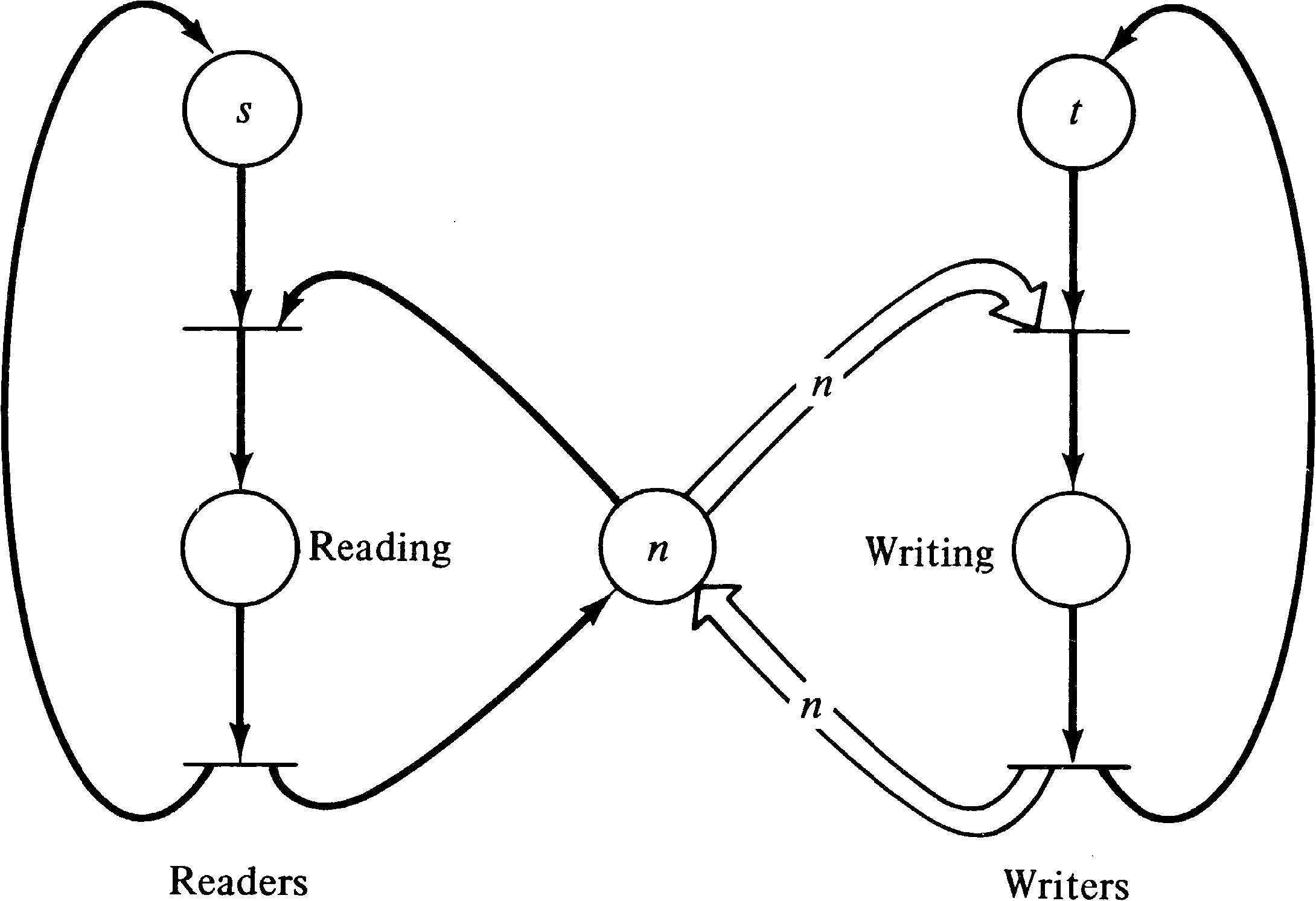
There are several variants of the readers/writers problem [Courtois et al. 1971], but the basic structure is the same. Processes are of two types: reader processes and writer processes. All processes share a common file, variable, or data object. Reader processes never modify the object, while writer processes do modify it. Thus writer processes must mutually exclude all other reader and writer processes, but multiple reader processes can access the shared data simultaneously. The problem is to define a control structure which does not deadlock or allow violations of the mutual exclusion criteria.
Figure 3.33 illustrates a solution when the number of reader
processes is bounded by n. In a system where the
number of reader processes is not bounded,
then only n readers may read at a time.
A problem occurs, however, if the number of readers is
unbounded and we wish to allow an unbounded number of
readers to simultaneously read. In this case, it can be
argued that it will be necessary for the readers to keep a
count of the number of readers reading. Each reader adds
one to this counter when it starts reading and subtracts one
when it finishes reading. This can be easily modeled by a
place with a number of tokens equal to the number of
readers. However, now in order to allow a writer to begin
writing, it is necessary that this counter be zero, i.e.,
the corresponding place be empty. There
is no mechanism in Petri nets which allows an unbounded
place to be tested for zero. Thus, it would appear that the
readers/writers problem with unbounded readers cannot be
solved with Petri nets. This is our first indication that
Petri nets may not be able to model all systems and is a
topic that deserves more study (Chapter 7).
3.4.8. P and V Systems
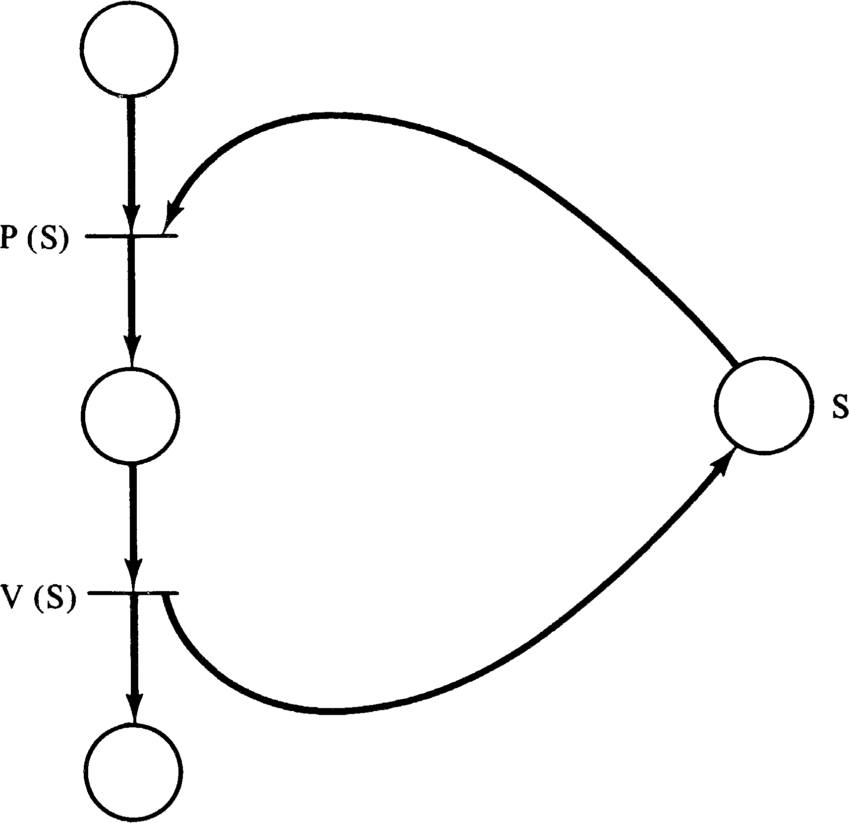
Most synchronization problems will not be solved directly by Petri nets but rather in terms of an established synchronization mechanism. In particular, one of the most popular synchronization mechanisms has been the P and V operations on semaphores originally defined by Dijkstra [1968]. A semaphore is data item which can take on only nonnegative integer values. The V operation increments the values by 1, while the P operation decrements the value by 1. The P operation can occur only when the semaphore value will remain nonnegative; if the semaphore value is zero, the P operation must wait until some other process executes a V operation. Both the P and V operations are defined to be primitive; no other operation may simultaneously modify the semaphore value.
These operations can
be easily modeled by Petri nets as shown in Figure 3.34.
Each semaphore is modeled by a place; the number of tokens
in that place indicate the value of the semaphore. A P
operation uses the semaphore place as an input; a V
operation uses the semaphore as an output.
The advantage of this ability to model P and V operations is
that many systems are written or designed using P and V
operations. For example, the Venus operating system [Liskov
1972] provides P and V operations as the basic interprocess
communication mechanism. These systems can thus be modeled
as Petri nets.
3.5. Other Systems
The systems which have been described so far are those which are the most obvious types of systems for Petri net modeling: computer hardware and software. But in large part this “obviousness” is a result of the fact that Petri nets have been defined and developed mainly for this purpose. Petri nets can also be directly applied to the modeling of a large number of other systems, some quite distinct from computer systems. In this section we briefly survey some of the systems to which Petri nets have been or could be applied.
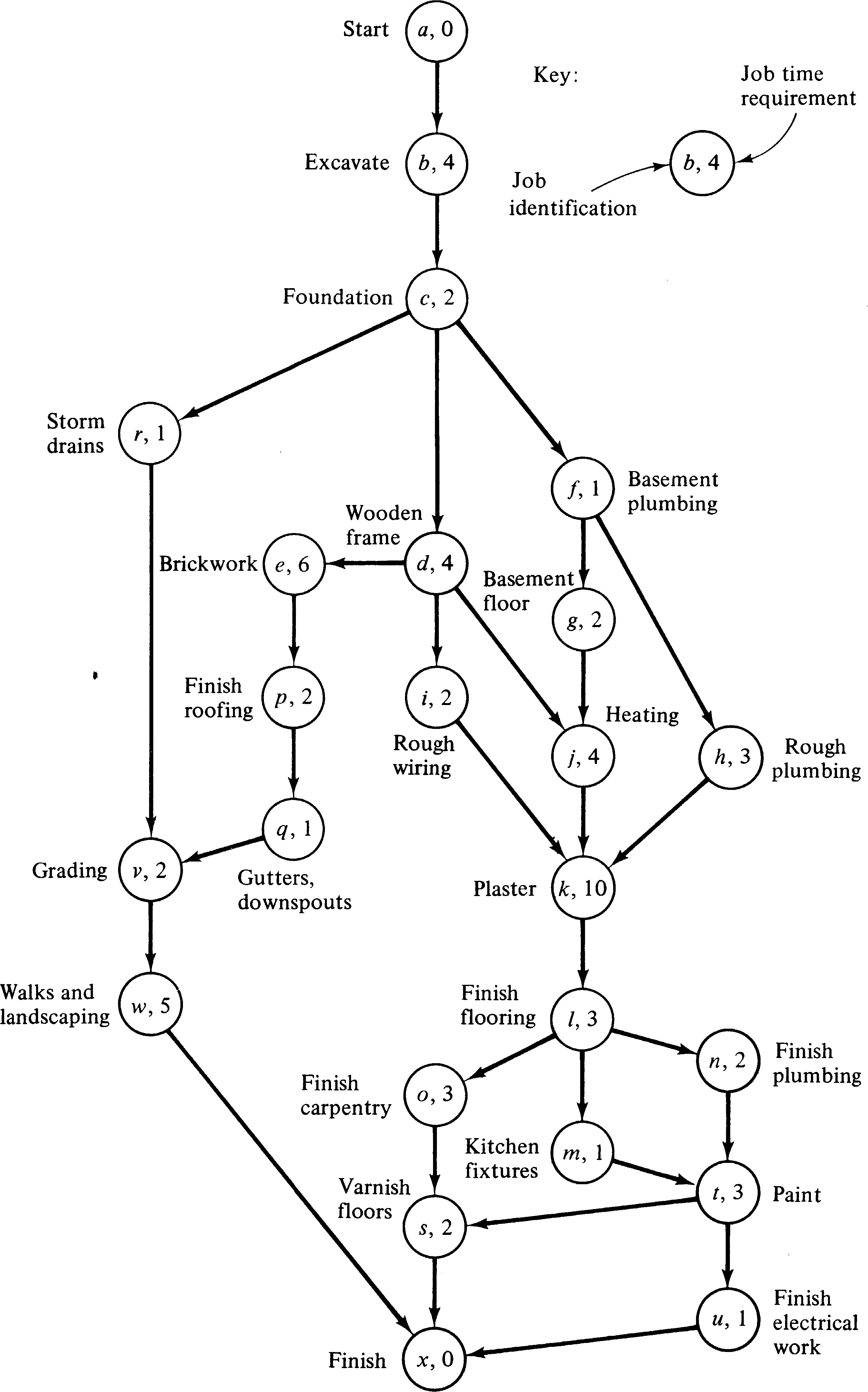
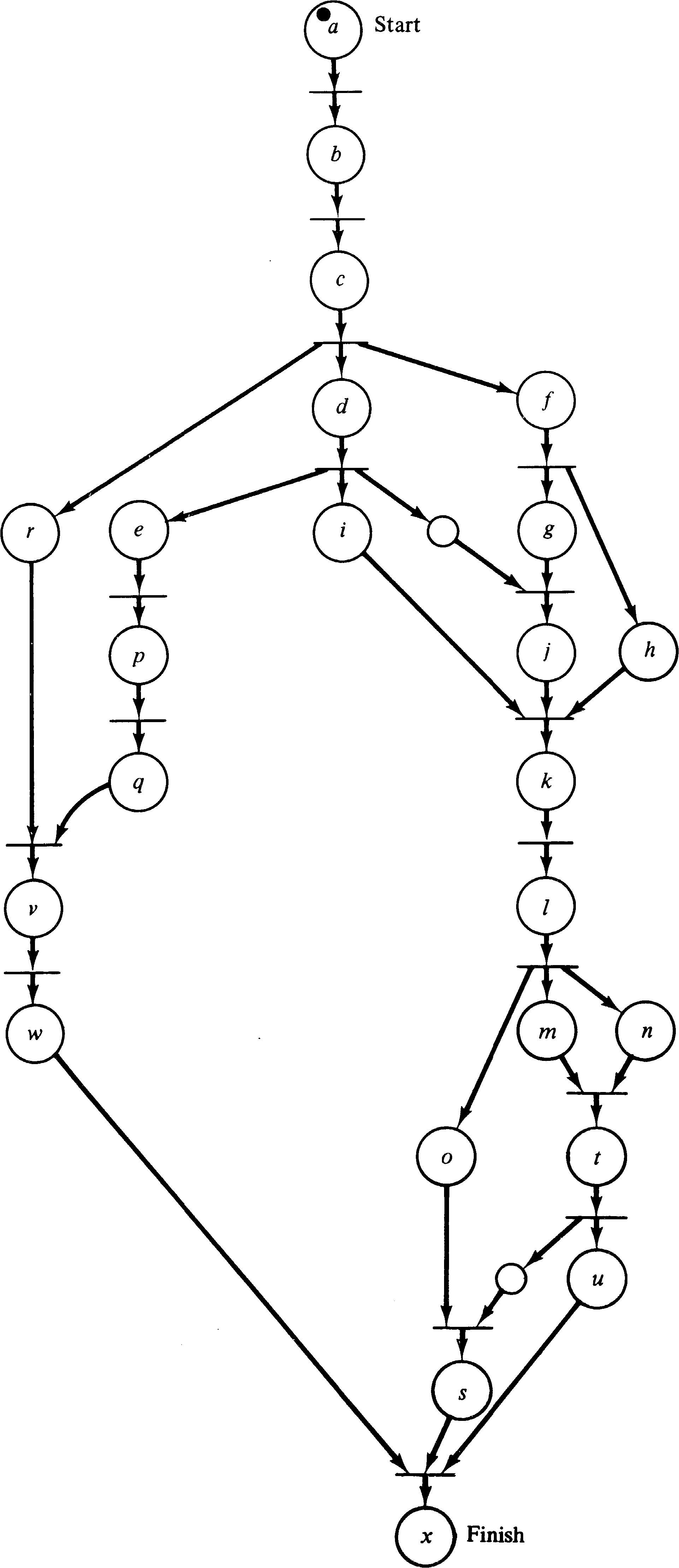
PERT charts have long been used in the planning and scheduling of large projects. A PERT chart is a graphical representation of the relationships between the various activities which make up a large project. A project consists of a number of activities; some activities must be completed before other activities can start. In addition a time is associated with each activity indicating the amount of time it will take. (Sometimes three times -- worst case, average, and best case -- are associated with each activity.) The activities are represented graphically by a node; arcs are used to connect activity nodes to show precedence requirements.
PERT charts show the same type of scheduling constraints
as Petri nets. We can easily convert a PERT chart to
a Petri net. Each activity in a PERT chart is represented
by a place, while the precedence constraints are represented
by the transitions. Figure 3.35 is a Petri net equivalent
of the PERT chart of Figure 3.36.
The Petri net is an excellent vehicle for representing the concurrency and precedence constraints of the PERT chart, but PERT charts also provide timing information which is useful for determining minimum project completion time, latest starting time for an activity which will not delay the project, and so on. A Petri net does not provide any of this type of information. The addition of timing information might provide a powerful new feature for Petri nets but may not be possible in a manner consistent with the basic philosophy of Petri nets. Research is needed on this extension to basic Petri nets [Sifakis 1977; Han 1978].
The pipeline of Section 3.3.2 is a special case of a production system [Hack 1972]. An assembly line is another example of a production system. Production systems and assembly lines can be modeled as Petri nets.
One of the early applications of Petri nets was as a tool
for the generation of optimal code for a CDC 6600
FORTRAN compiler. The approach suggested by Shapiro and
Saint [1970] was to model the FORTRAN program as a Petri
net, in a manner similar to the flowchart modeling of
Section 3.4.1. Then the individual statements of the
program are examined to determine the minimal precedence
constraints between statements, allowing the Petri net to
drop some of the artificial sequencing constraints of the
program. These artificial constraints are introduced
because the FORTRAN programmer must express the program as a
total ordering of statements, even though only a partial
ordering is necessary. For example, consider the following
three statements.
| 10 x | = | x + 1 |
| 20 y | = | y + 1 |
| 30 z | = | x + y |
The result of this analysis is a Petri net which represents
the program with only the minimal sequencing constraints,
i.e., allowing maximal parallelism. Now the
problem is to compile this program. This requires mapping
variables into registers and ordering the instructions to
produce a totally ordered sequence of machine language
instructions. The 6600 is a multiple register, multiple
functional unit computer, as described in Section 3.3.3.
Since the functional units can execute in parallel on
separate instructions, it is very important to generate
instructions in an order which maximizes the parallelism in
the execution of the functional units. This is also
affected by the assignment of variables to registers. The
Petri net model of the program representing the constraints
of the program is combined with a Petri net model of the CDC
6600 control unit, representing the constraints imposed by
the hardware. This composite net then represents all
possible sequences of instructions which can execute on the
hardware and perform the algorithm of the program. This net
is then executed to produce all such sequences of
instructions. Two (or more) sequences are created whenever
two (or more) transitions are simultaneously enabled.
Firing one transition will produce one sequence; firing the
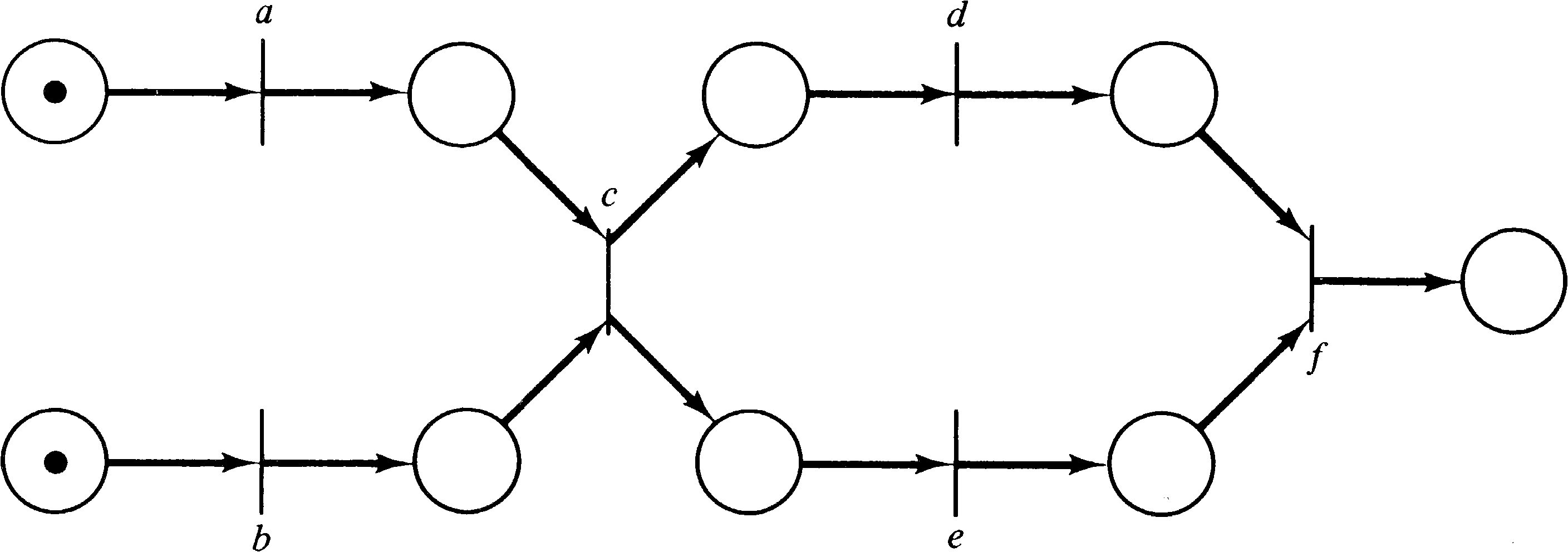
other produces another sequence. For example, the Petri net
of Figure 3.37 represents the sequences a b c d e f,
b a c d e f, a b c e d f, and
b a c e d f. As these
sequences are produced, the amount of time to execute each
is computed, and the fastest sequence is generated by the
compiler for actual execution later.
Another suggested use for Petri nets has been in the modeling and analysis of communication protocols [Merlin 1975]. Computer networks and systems of distributed processes require the ability to transmit information from computer to computer. This intrinsically involves parallelism and therefore falls into the class of problems for which Petri nets have been defined. Farber and his students [Merlin 1974; Postel 1974; Merlin and Farber 1976; Postel and Farber 1976] have developed methodologies for the specification, design, and analysis of simple communications protocols using Petri nets and similar models.
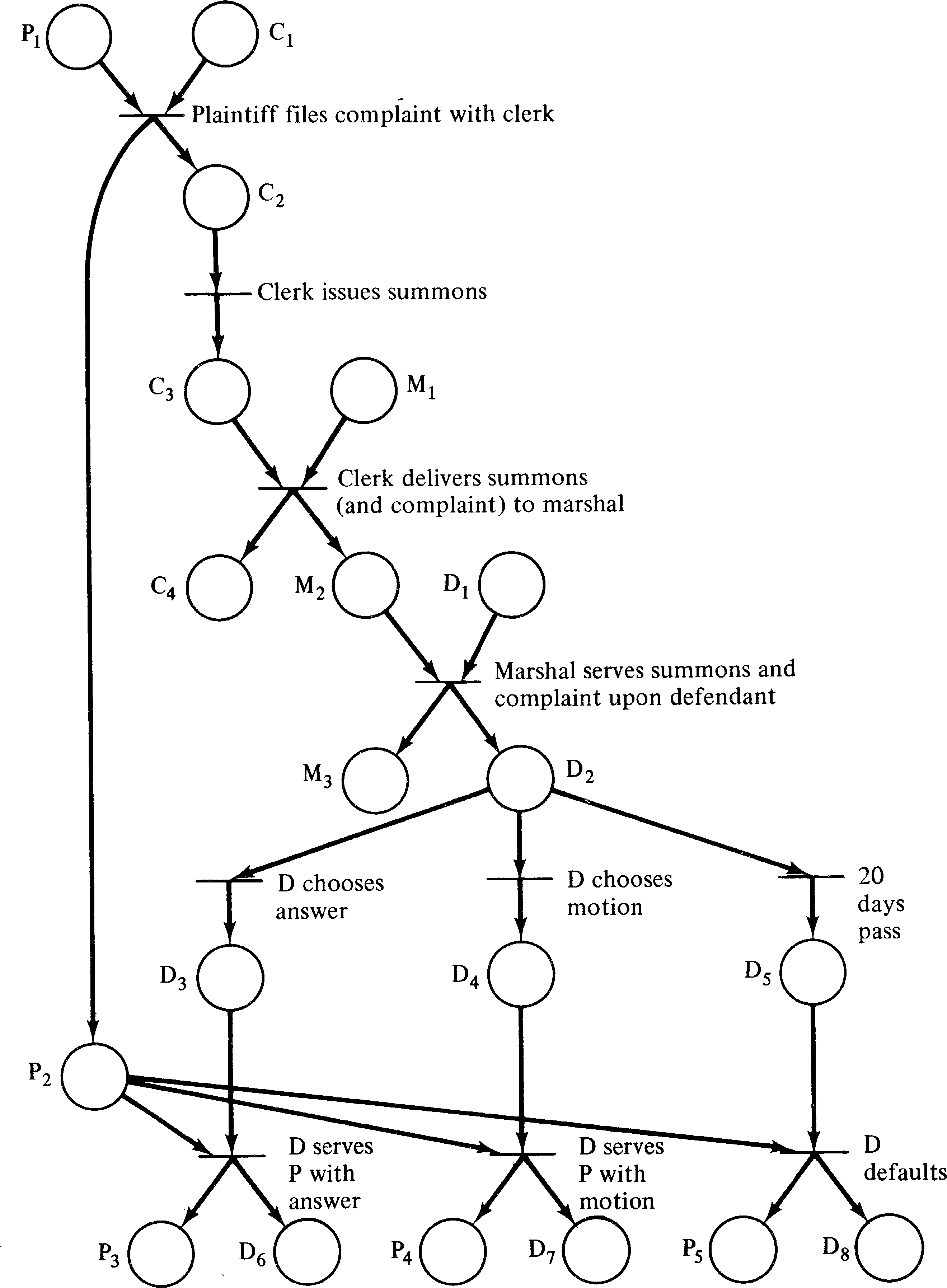
Meldman and Holt [1971] have suggested that legal
systems may be modeled by Petri nets. In these systems,
several actors (judges, lawyers, defendants, clerks, and so
on) may concurrently perform activities which relate to a
particular legal matter. The activities and their
relationships can be represented by a Petri net. For
example, Figure 3.38 is a model of the initial stages of a
civil action.
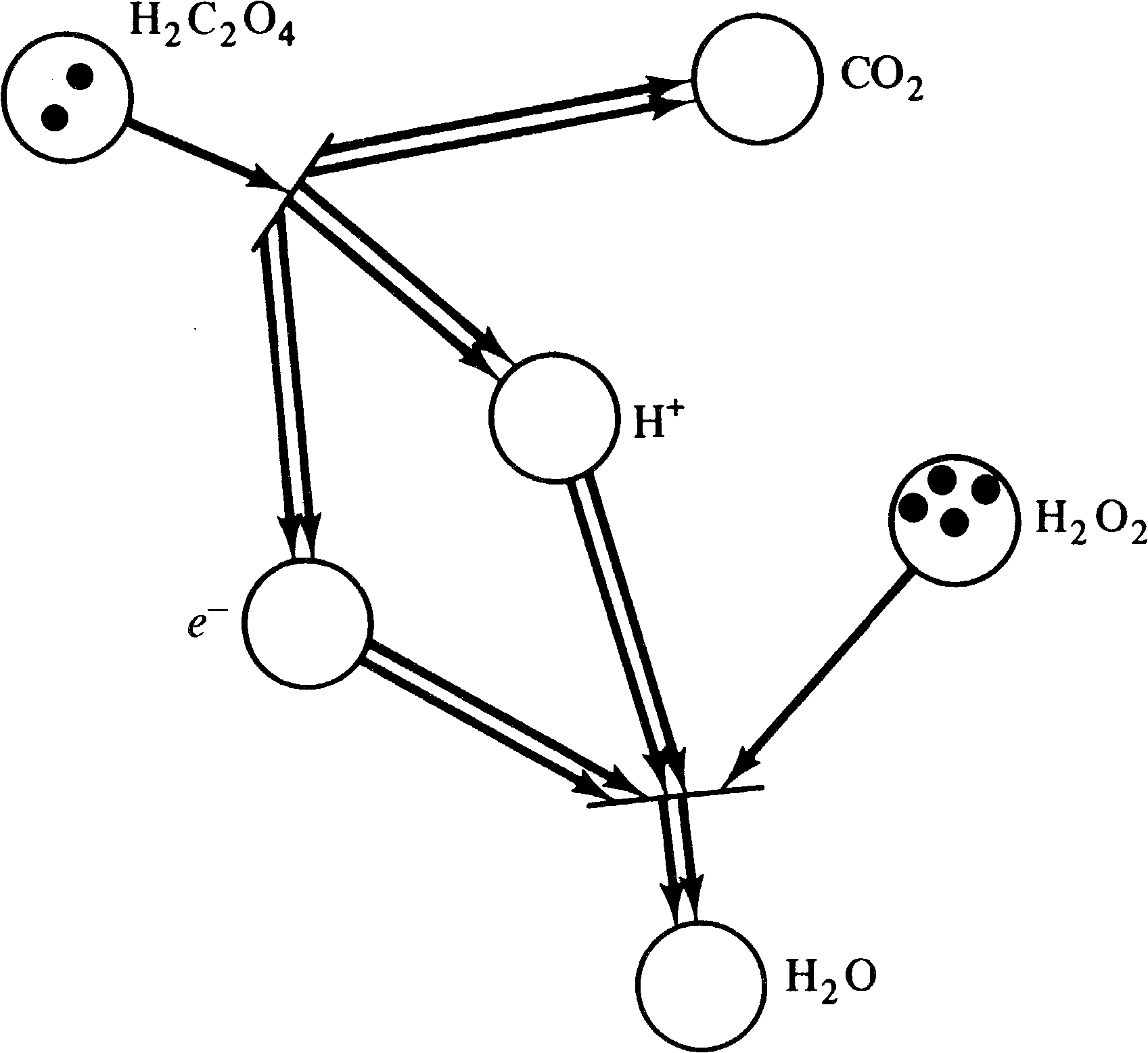
Chemical systems are another example of a system which
can be modeled by Petri nets. Chemical equations are
modeled by transitions; reactants are modeled by places.
The number of tokens in a place indicate the amount of that
reactant in the system. For example, the Petri net in
Figure 3.39 represents the two chemical equations
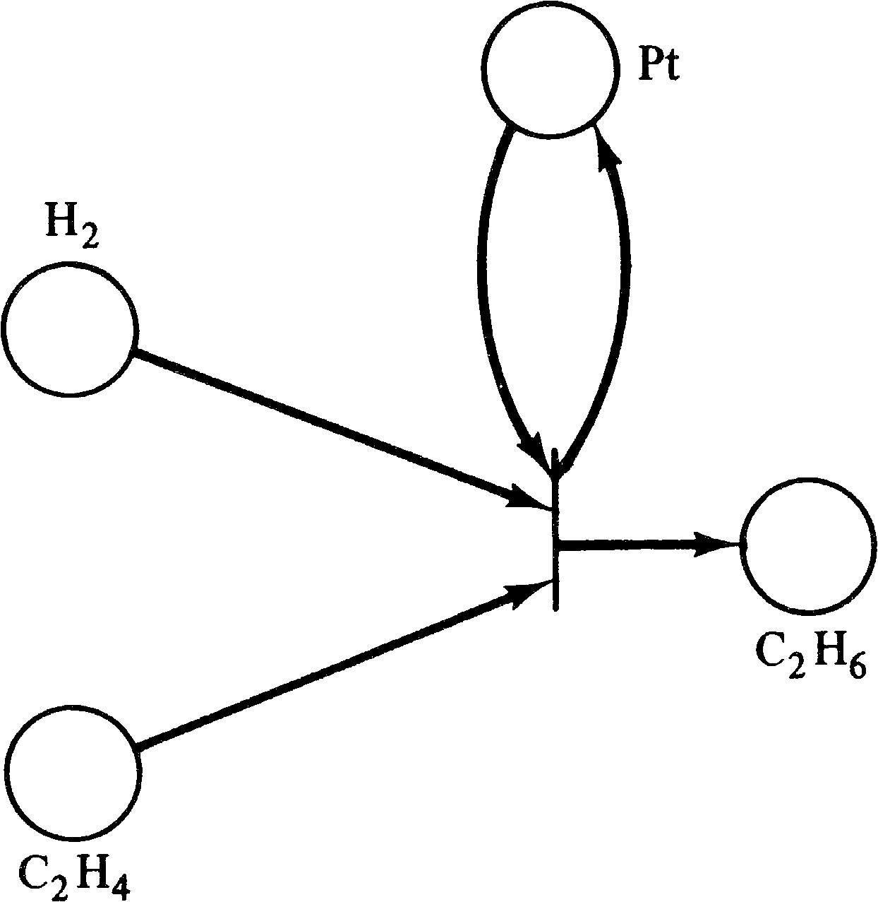
| H2 C2 O4 → 2 CO2 + 2 H+ + 2e− |
| e− + 2 H+ + H2 O2 → 2 H2 O |
Other systems which could be modeled by Petri nets include queueing networks (where the queues would be represented by places and the jobs by tokens), brain models (neuron firings would be modeled by transition firings), propositional calculus [Genrich 1975; Genrich and Lautenbach 1978] (the places represent literals, and the transitions combine them to define clauses in conjunctive normal form), and many others. The list is limited in the main by the time and imagination of the modeler, and not by the properties of the Petri net model.
However, we have seen at least one example (the
readers/writers problem) which may not be able to be modeled
by a Petri net. Also, although modeling as a Petri net may
aid the description of a system, we need to develop analytic
tools which will allow us to examine a Petri net and
determine properties of the Petri net. This leads us to the
next chapter, in which we present analysis methods for Petri
nets.
Exercises
Most of the research on Petri nets has been on analysis, not modeling. Surveys of applications of Petri nets to modeling have appeared in [Peterson 1977; Agerwala 1978]. Hardware modeling was considered in [Dennis 1970a; Huen and Sieworek 1975]. The paper by Shapiro and Saint [1970] combines hardware and software modeling to implement a compiler. The notes by Cooprider [1976] are concerned with modeling software systems by Petri nets. Hack's Master's thesis [Hack 1972] considered the modeling of production schemata which includes assembly line-type systems.
Baer and Ellis [1977] used Petri nets to model a compiler, while Noe [1971] and Best [1976] used Petri nets to model operating systems. Noe and Kehl [1975] have modeled the hardware of a computer system. Azema et al. [1975], Azema et al. [1976], and Foo and Musgrave [1975] have suggested the use of Petri nets for design automation.
The work of Noe and Nutt is specifically directed at
modeling systems to determine performance properties. Their
work [Noe 1971; Nutt 1972a; Nutt 1972b; Noe and Nutt 1973]
eventually led to the development of a model, E-nets, which
is related to Petri nets.
3.7. Topics for Further Study
| Home | Comments? |