| Home | Up | Questions? |
In the last chapter we demonstrated the modeling power of Petri nets. Petri nets are capable of modeling a large variety of systems, properly representing the interactions between the various actions which can occur. The major strength of Petri nets is, of course, in the modeling of systems which may exhibit concurrency; concurrency is modeled in a natural and convenient way. A Petri net model can be used to represent and communicate the design of a concurrent system.
However, modeling by itself is of little use. It is
necessary to analyze the modeled system. This
analysis will hopefully lead to important insights into the
behavior of the modeled system. Thus, we turn now to
presenting analysis techniques for Petri nets. Several
techniques have been developed for the analysis of Petri
nets, but many problems in the analysis of Petri nets are
still open. To better evaluate the usefulness of the
analysis techniques which have been developed, we first
consider what types of problems may need to be solved for
Petri nets. The objective of the analysis of a Petri net is
to determine the answer to a question about the Petri net.
What types of questions might be asked about Petri nets?
4.1. Analysis Problems for Petri Nets
The following properties and questions have been considered
in the literature about Petri nets. We define and
illustrate these properties here; we show the appropriate
analysis techniques in the second portion of this chapter.
4.1.1. Safeness
For a Petri net which is to model a real hardware device, one of the more important properties is safeness. A place in a Petri net is safe if the number of tokens in that place never exceeds one. A Petri net is safe if all places in the net are safe.
The original Petri nets were safe by definition, since a transition could not fire unless all of its output places were empty (and multiple arcs were not allowed). This was motivated by the interpretation of a place as representing a condition. A condition, being a logical statement, is either true (represented by a token in the place) or false (represented by an absence of a token); multiple tokens have no interpretation. Thus, the marking of each place should be safe under an interpretation as conditions and events.
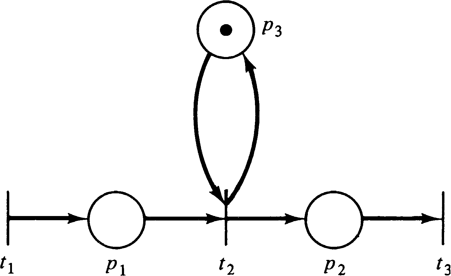
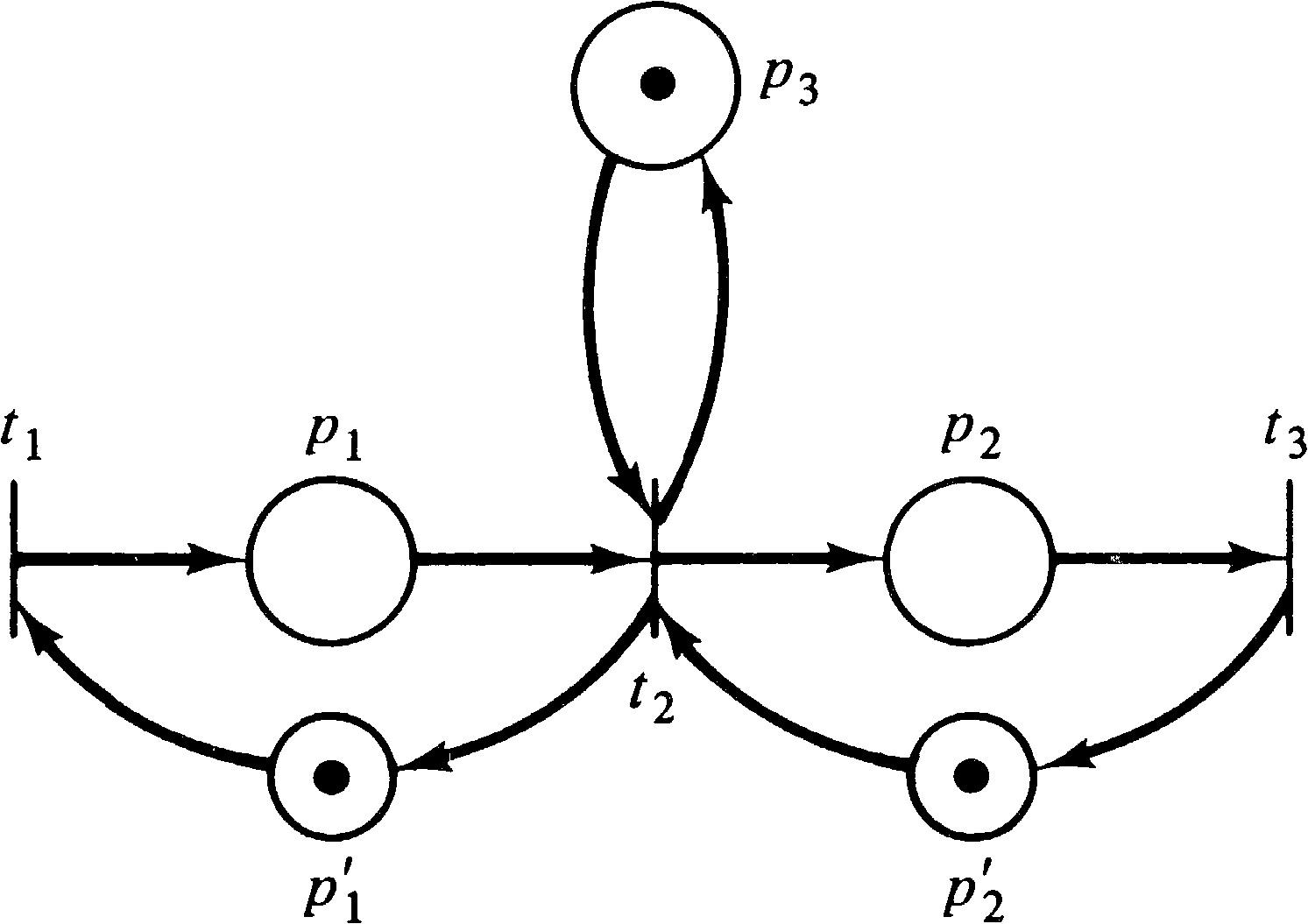
As long as a place is not a multiple input or multiple output of a transition, it is possible to force that place to be safe. A place pi which is to be forced to be safe is supplemented by another place pi′ . Transitions which use pi as an input or output are modified as follows:

Safeness is a special case of the more general boundedness property. Some thought about the real limitation to implementing places in hardware shows that it is not necessary to require safeness. Safeness allows a place to be implemented with a flip-flop, but, more generally, a counter could be used. However, any such hardware counter would be limited in the maximum number which could be represented. A place is k-safe or k-bounded if the number of tokens in that place cannot exceed an integer k.
A place which is 1-safe is simply called safe. Notice that the bound k on the number of tokens which can be in a place may be a function of the place (e.g., place p1 may be 3-safe while place p2 is 8-safe). However, if a place pi is k -safe, then it is also k′ -safe for all k′ ≥ k. Since there are only a finite number of places, we can pick k to be the maximum of the bounds of each place and define a Petri net to be k -safe if every place of the net is k -safe.
We may sometimes be concerned only with whether or not the
number of tokens in a place is bounded or not, but we are
not concerned with the specific value of the bound. A place
is bounded if it is k -safe for some k; a
Petri net is bounded if all places are bounded. A bounded
Petri net could be realized in hardware, while a Petri net
with an unbounded place could not in general be implemented
in hardware. (Remember that these definitions are
independent of interpretation. In implementation a place
might represent some entity which is bounded, although the
net structure itself does not reflect this fact.)
4.1.3. Conservation
Petri nets can be used to model resource allocation systems. For example, a Petri net can model the requests, allocations, and releases of input/output devices in a computer system. In these systems some tokens may represent the resources. A set of three line printers is represented by a place with an initial marking of three tokens. A request for a line printer is a transition which has this place as an input; the line printer is later released by a transition with an output to the line printer place.
For these types of Petri nets, among others, conservation is an important property. We would like to show that tokens which represent resources are neither created nor destroyed. The simplest way to do this would be to require that the total number of tokens in the net remain constant.
| Σ | μ′(pi) | = | Σ | μ(pi). |
| pi ∈ P | pi ∈ P |
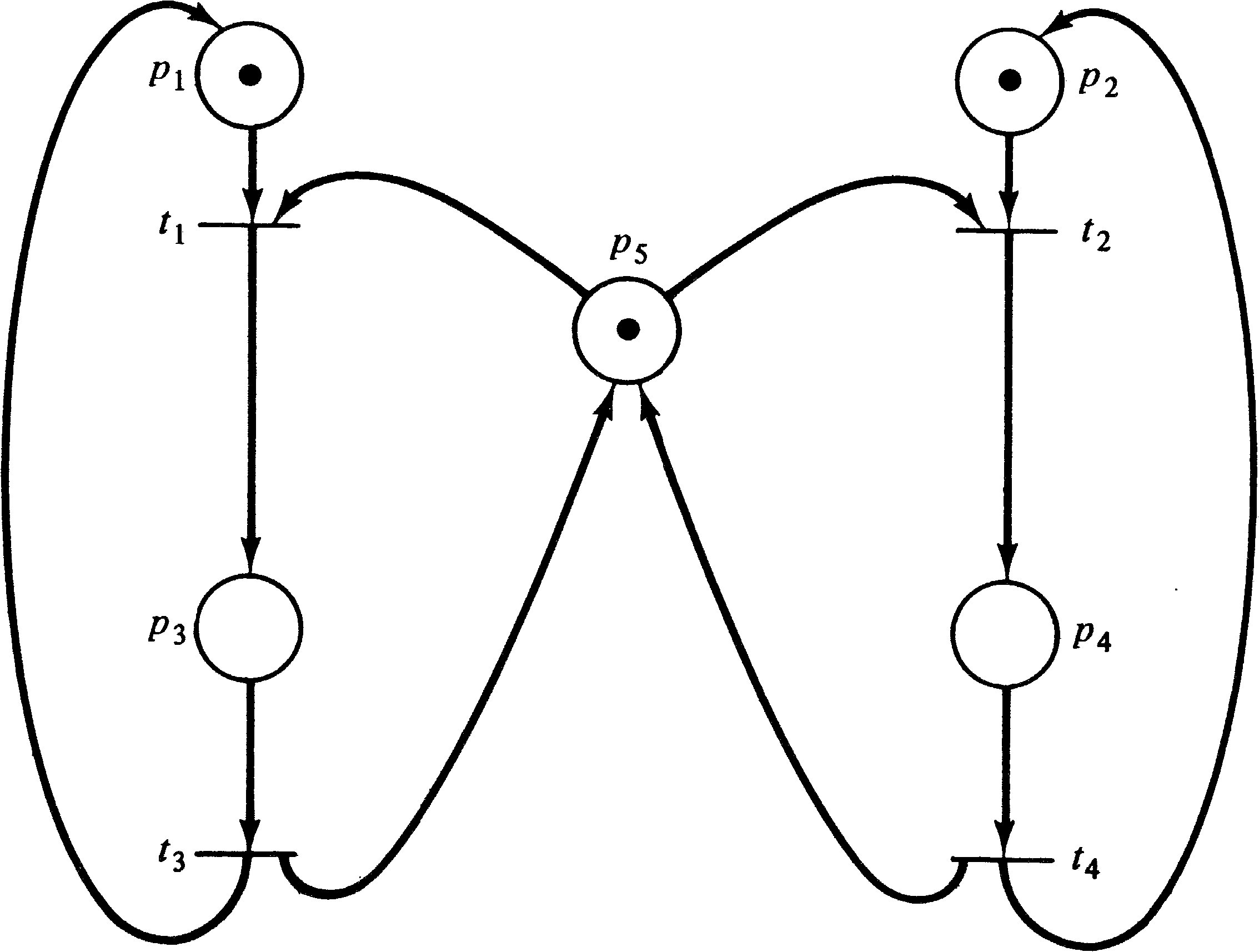
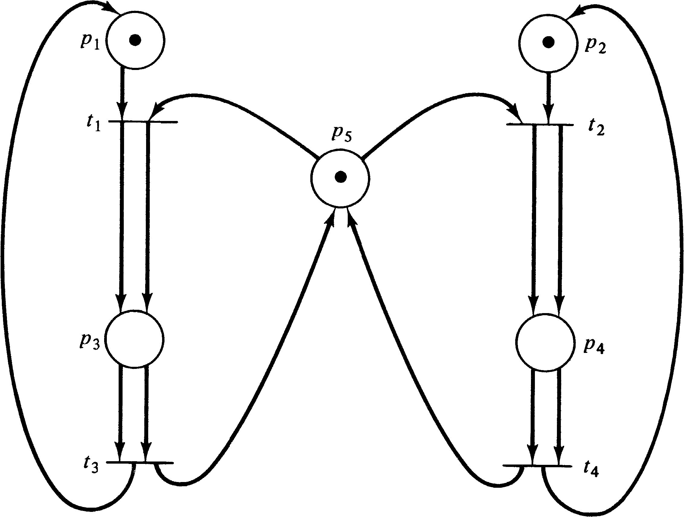
For a broader view, however, consider Figure 4.3. Figure 4.3 is not
strictly conservative since the firing of either transition t1
or t3 will decrease the number of tokens by one, while firing
transition t2 or t4 will add a token
to the marking. We could, however, convert the Petri net of Figure 4.3
to the net of Figure 4.4, which is strictly conservative.
A Petri net should conserve the resources which it is modeling. However, there is no one-to-one mapping between tokens and resources. Some tokens represent program counters or other items; other tokens may represent several resources with one token. This token is later used to create multiple tokens (one per resource) by firing a transition with more outputs than inputs. In general, we would like to define a weighting of tokens. The weighted sum for all reachable markings should be constant. Tokens which are not important can be assigned a weight of 0; other tokens can be assigned weights of 1, 2, 3, or any other integer. (Rational numbers would be acceptable since the weightings could be multiplied by a common denominator to define an integer weighting. Irrational weights would not seem to be needed.)
A token is defined by its place in the net, and all tokens in a place are indistinguishable. Thus the weights are associated with each place of the Petri net. A weighting vector w = ( w1, w2, …, wn ) defines a weight wi for each place pi ∈ P.
| Σ | wi ⋅ μ′(pi) | = | Σ | wi ⋅ μ(pi). |
| i | i |
The Petri net of Figure 4.3 is therefore conservative since
it is conservative with respect to (1, 1, 2, 2, 1). The
Petri net of Figure 4.5 is not conservative.
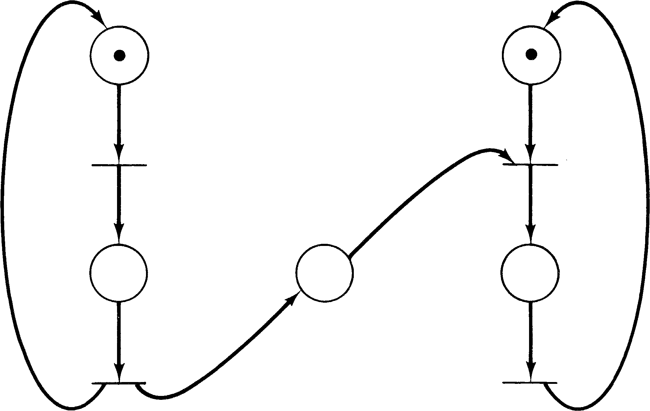
The motivation for considering conservation in a Petri net
was resource allocation in a computer operating system.
Another problem which may arise in resource allocation for a
computer system is deadlock. Deadlock has been the
subject of a number of studies in computer science [Hebalkar
1970]. A simple example can best illustrate the problem:
Consider a system with two different resources q and
r and two processes a and b. If both
processes need both resources, it will be necessary to share
them. To accomplish this we require each process to request
a resource and later release it. Now suppose process
a first requests resource q and then resource
r and finally releases both q and r.
Process b is similar but first requests r and
then q. Figure 4.6 illustrates these two processes
and the resource allocation with a Petri net.
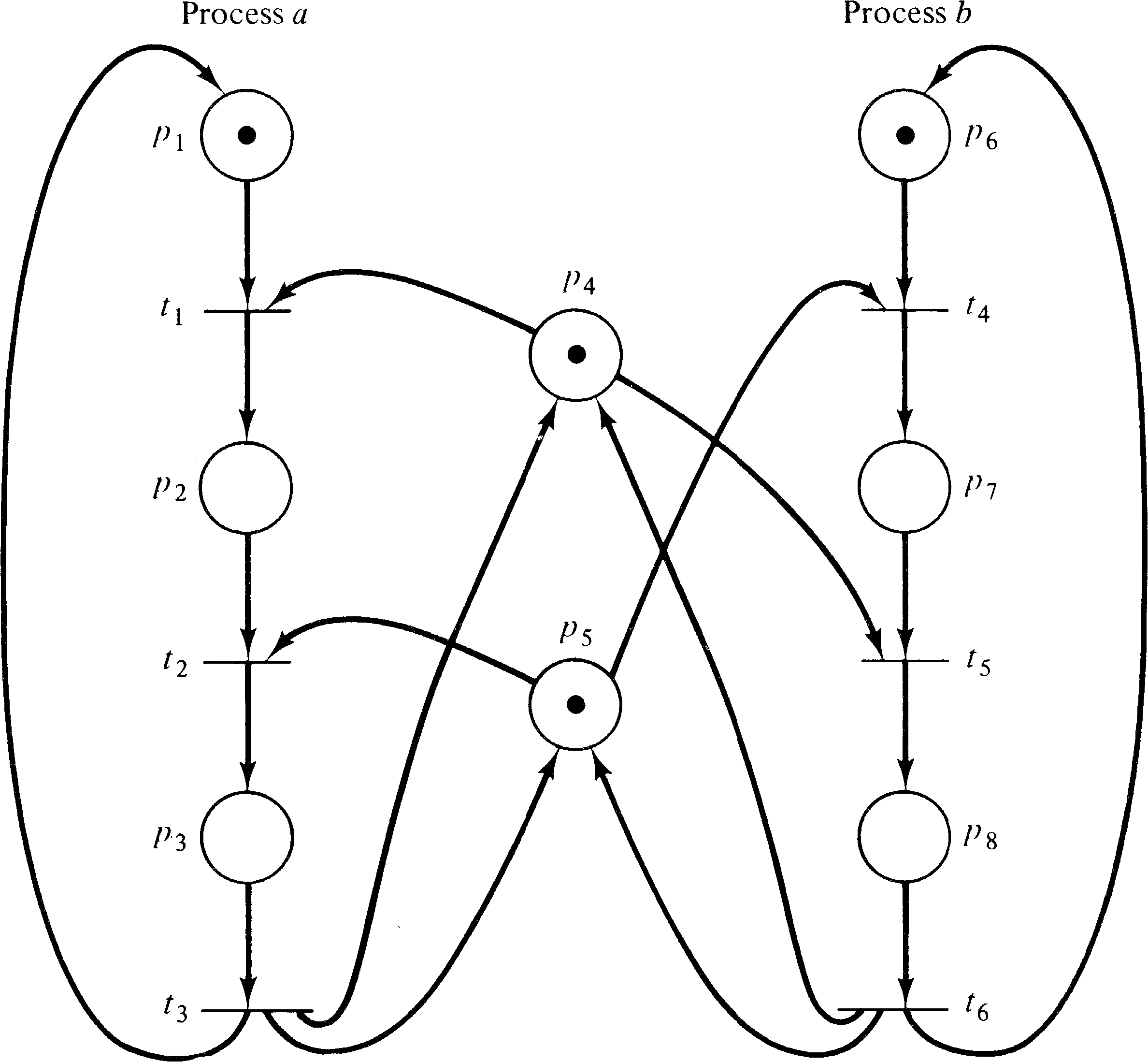
The initial marking indicates resources q ( p4 ) and r ( p5 ) are available and processes a and b are ready. One execution of this net is t1 t2 t3 t4 t5 t6; another is t4 t5 t6 t1 t2 t3. Neither of these executions results in deadlock. However, consider the sequence which starts t1 t4: Process a has q and wants r; process b has r and wants q. The system is deadlocked; neither process can proceed.
A deadlock in a Petri net is a transition (or a set of transitions) which cannot fire. In Figure 4.6, deadlock occurs if transitions t2 and t5 cannot fire. A transition is live if it is not deadlocked. This does not mean that the transition is enabled but rather that it can be enabled. A transition tj of a Petri net C is potentially fireable in a marking μ if there exists a marking μ′ ∈ R ( C, μ ) and tj is enabled in μ′ . A transition is live in a marking μ if it is potentially fireable in every marking in R ( C, μ ) . Thus if a transition is live, it is always possible to maneuver the Petri net from its current marking to a marking which would allow the transition to fire.
There are other concepts, related to liveness, which have been considered in studies of deadlock [Commoner 1972]. These can be categorized as levels of liveness and can be defined for a Petri net C with marking μ as
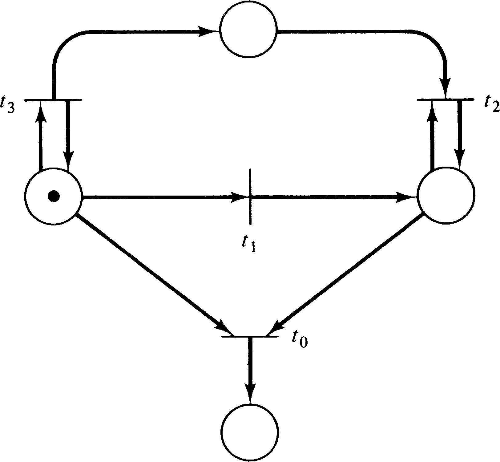
As an example of these levels of liveness, consider Figure
4.7. Transition t0 can never fire; it is dead.
Transition t1 can fire exactly once; it is live at
level 1. Transition t2 can be made to fire an
arbitrary number of times, but the number of times is
dependent on the number of times that t3 fires.
If we want to fire t2 five times, we fire t3 five times, then t1, and then t2 five times.
However, once t1 fires (and t1 must fire
before t2 can fire), the number of times
t2 can fire is fixed. Thus, t2 is live
at level 2, but not at level 3. Transition t3, on
the other hand, can be fired an infinite number of times and
so is live at level 3, but not at level 4, since once
t1 fires t3, can no longer fire.
Most of the problems which have been mentioned so far are concerned with reachable markings. Perhaps the simplest problem (to state) is the reachability problem.
The reachability problem is perhaps the most basic Petri net analysis problem; many other analysis problems can be stated in terms of the reachability problem. For example, for the Petri net of Figure 4.6, deadlock can occur if the state (0, 1, 0, 0, 0, 0, 1, 0) is reachable.
Figure 4.8 shows a Petri net which purports to solve the mutual exclusion problem -- places p4 and p9 are expected to be mutually exclusive. We wish to know if any state is reachable with p4 = 1 and p9 = 1 . This problem is similar to reachability but is slightly different; it is called the coverability problem. A marking μ′′ covers a marking μ′ if μ′′ ≥ μ′ .
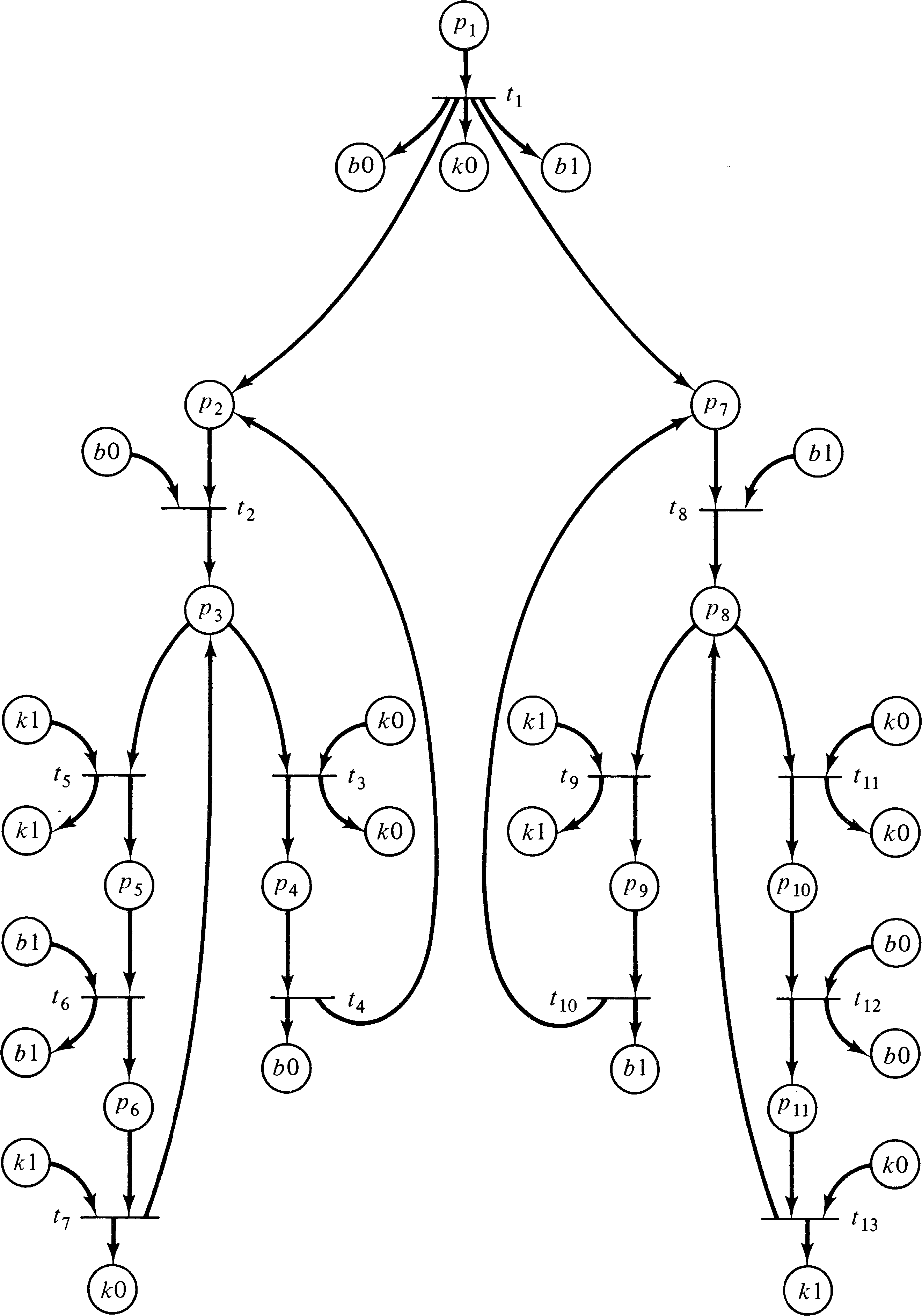
Another possible use of reachability-type problems would be to ignore the contents of some places, concentrating only on matching or covering the contents of a few important places. For example, in the Petri net of Figure 4.8, our interest is confined to places p4 and p9; the markings of the remaining places are not important. Thus, we can consider reachability or coverability modulo a set of places. These problems are called the submarking reachability and submarking coverability problems.
These problems can be further complicated by wanting to know
reachability or coverability for a set of markings, the
set reachability and set coverability problems.
However, if the set is finite, the set problems can
obviously be solved by repeated solutions of the
reachability and coverability problems for one marking.
4.1.6. Firing Sequences
Another approach to analysis which has been suggested
concentrates on sequences of transition firings
rather than on states. This is related to liveness, since
we may ask, Can transition tj be fired
(i.e., is it dead)? But more generally we may
want to determine if a specific sequence of transition
firings is possible or if any of a set of firing sequences
is possible. In Figure 4.8, for example, mutual exclusion
would be violated if the sequence t3 t9
can occur, or if t4 t10 can occur, or,
more generally, if t3 σ t9 can
occur, where σ is any sequence of firings not including
t4. These analysis questions introduce the
concept of languages of Petri nets and will be
investigated in more detail in Chapter 6.
4.1.7. Equivalence and Subset Problems
A final class of problems arises from optimization considerations. If a Petri net exhibits a certain behavior, as indicated by its set of transition firing sequences and its reachability set, can the Petri net be changed (optimized) without affecting its behavior? This may involve deleting dead transitions (which can never be fired) and dead places (which can never be marked) or perhaps the redefinition of some transitions. Can we show that two different marked Petri nets with the same number of transitions (but perhaps different numbers of places) will generate the same sequence of transition firings or that two different marked Petri nets with the same number of places (but perhaps different numbers of transitions) will generate the same reachability set? This might allow us to modify Petri nets to increase parallelism, decrease the cost of implementation, or other optimizations.
In these cases, we are concerned with determining if two
Petri nets are equivalent or if one is a subset of the
other. We must be careful with these problems to define the
notion of equivalence or containment carefully. If we define
equivalence as equal reachability sets, then we cannot
change the number of places, while if we require equality of
sets of transition firing sequences, we may not be able to
change transitions. Our definition of the problem is
therefore quite important.
4.2. Analysis Techniques
There are other problems that can be considered, but those presented here are the most common problems mentioned in the literature; we mention others as it becomes necessary to introduce them. You can see that there are a number of problems which may need solution for Petri nets. Can we develop analysis techniques to solve these problems? In particular, of course, we want to develop techniques which can be easily implemented on a computer, to allow automatic analysis of modeled systems.
Two major Petri net analysis techniques have been suggested,
and we present these in this section. These techniques
provide solution mechanisms for some of the above problems.
The major analysis technique which has been used with Petri
nets is the reachability tree; the other technique
involves matrix equations. We discuss each of these in
turn.
4.2.1. The Reachability Tree
The reachability tree represents the reachability set of a
Petri net. As an example, consider the marked Petri net of
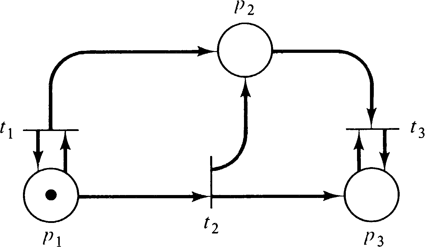
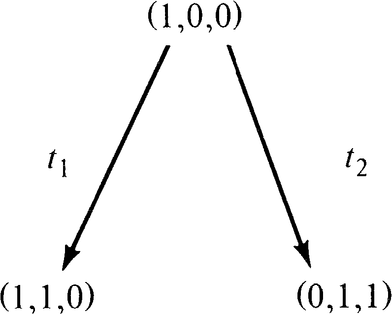
Figure 4.9. The initial marking is (1, 0, 0). In this
initial marking two transitions are enabled: t1
and t2. Since we wish to consider the entire
reachability set, we define new nodes in the reachability
tree for the (reachable) markings which result from firing
both transitions. An arc, labeled by the transition fired,
leads from the initial marking to each of the new markings
(Figure 4.10). This (partial) tree shows all markings which
are immediately reachable from the initial marking.
Now we must consider all markings reachable from these new
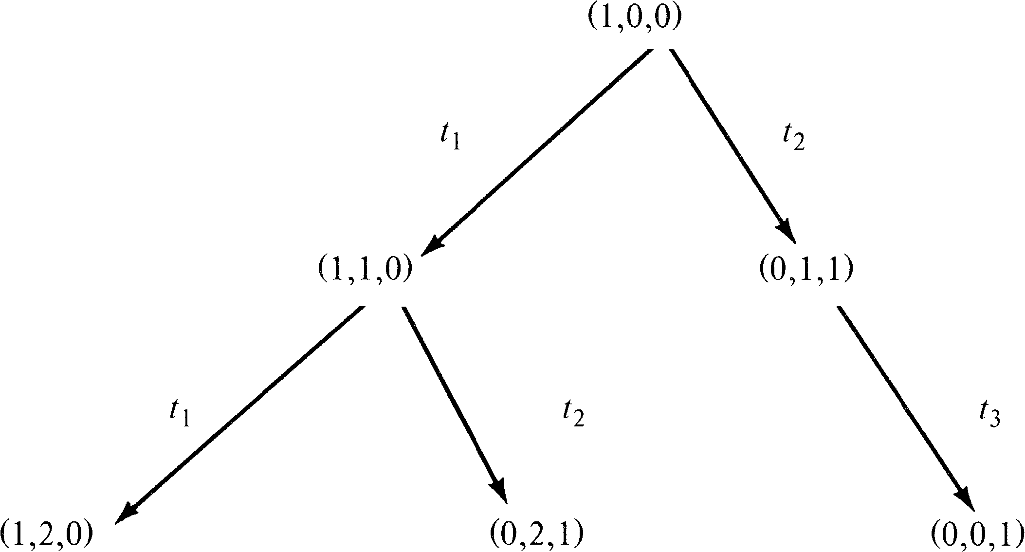
markings. From marking (1, 1, 0), we can again fire
t1 [giving (1, 2, 0)] and
t2 [giving (0, 2, 1)];
from (0, 1, 1) we can fire t3 [giving (0, 0, 1)].
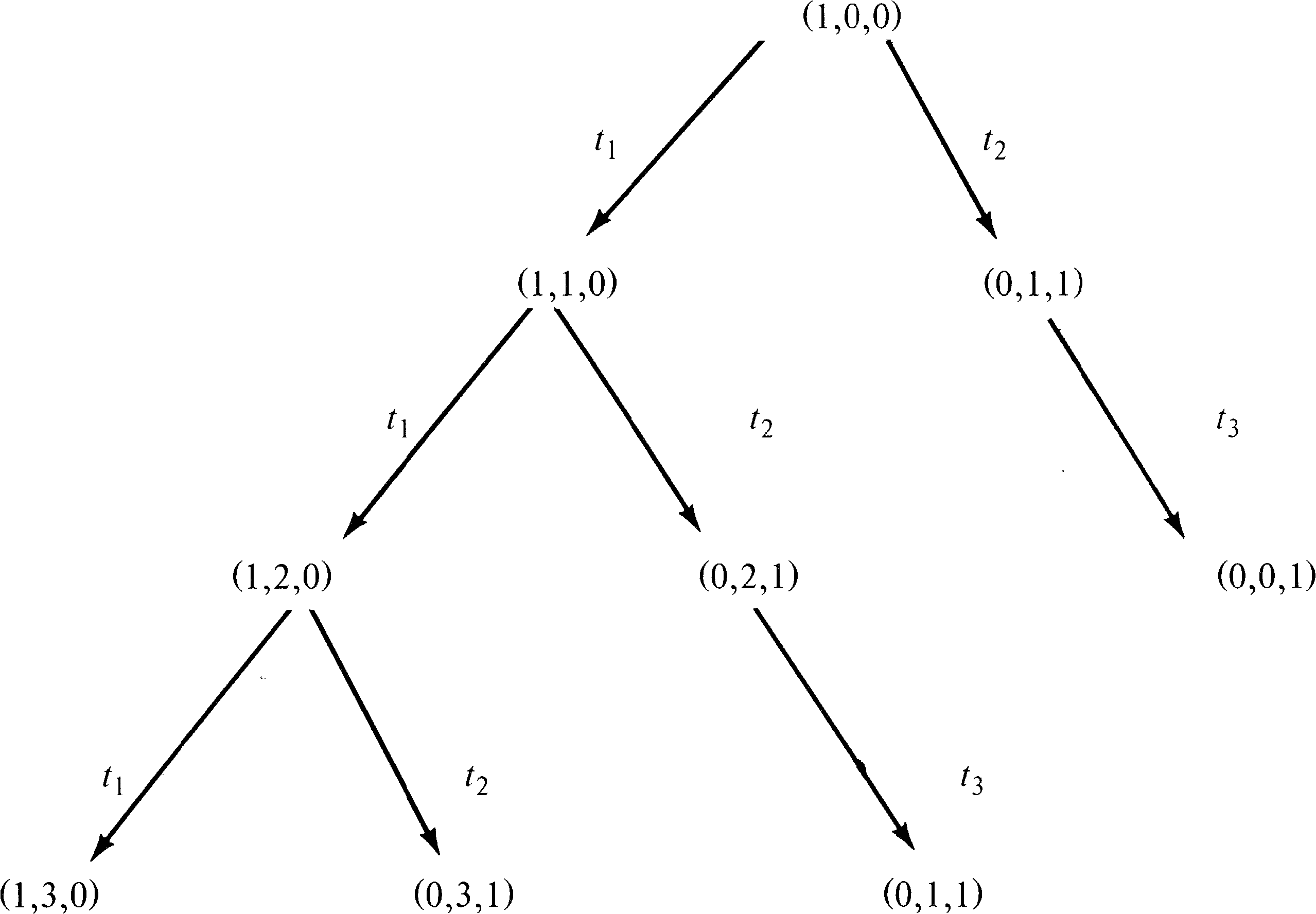
This produces the tree of Figure 4.11. With the
three new markings, we must repeat this process, producing
new markings to add to the tree as shown in Figure 4.12.
Notice that the marking (0, 0, 1) is dead; no transitions
are enabled, and so no new markings are produced in the tree
by this dead marking. Also notice that the marking produced
by firing t3 in (0, 2, 1) is (0, 1, 1); the
marking (0, 1, 1) was also produced directly from the
initial marking by firing t2.
If this procedure is repeated over and over, every reachable
marking will eventually be produced. However, the resulting
reachability tree might well be infinite. Every marking in
the reachability set will be produced, and so for any Petri
net with an infinite reachability set, the corresponding
tree would also be infinite. Even a Petri net with a finite
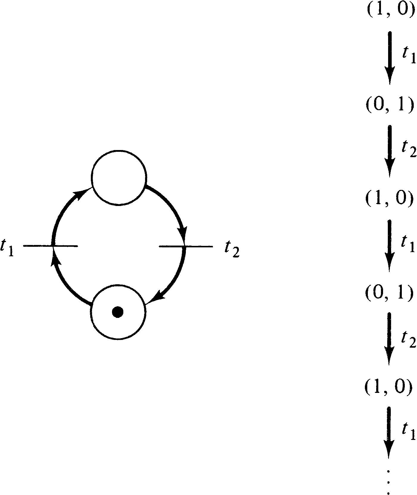
reachability set can have an infinite tree (Figure 4.13).
The tree represents all possible sequences of transition
firings. Every path in the tree, starting at the root,
corresponds to a legal transition sequence. If the tree is
going to be a useful analysis tool, we must find a means to
limit it to a finite size. (Notice that if the
representation of an infinite set is finite, then an
infinite number of markings must be mapped onto the same
representation. This will, in general, result in a loss of
information, which may mean that some properties of Petri
nets cannot be determined, but this depends on how the
representation is done.)
The reduction to a finite representation is accomplished by several means. We must find a means of limiting the new markings (called frontier nodes) introduced at each step. This is helped by dead markings -- markings in which no transition is enabled. These dead markings are known as terminal nodes. Another class of markings are those markings which have previously appeared in the tree. These duplicate markings are known as duplicate nodes, and no successors of a duplicate node need be considered; all these successors will be produced from the first occurrence of the marking in the tree. Thus in the tree of Figure 4.12, the marking (0, 1, 1) which results from the sequence t1 t2 t3 does not produce any further nodes in the tree, since it occurred earlier in the tree as a result of the sequence t2 from the initial marking.
One final means is used to reduce the reachability tree to a finite representation. Consider a sequence of transition firings σ which starts at a marking μ and ends at a marking μ′ with μ′ > μ . The marking μ′ is the same as the marking μ except that it has some “extra” tokens in some places, that is, μ′ = μ + ( μ′ − μ ) and ( μ′ − μ ) > 0 . Now, since transition firings are not affected by extra tokens, the sequence σ can be fired again, starting in μ′, leading to a marking μ′′ . Since the effect of the sequence of transitions σ was to add μ′ − μ tokens to the marking μ, it will also add μ′ − μ tokens to the marking μ′, so μ′′ = μ′ + ( μ′ − μ ) or μ′′ = μ + 2 ( μ′ − μ ) . In general, we can fire the sequence σ n times to produce a marking μ + n ( μ′ − μ ) . Thus, for those places which gained tokens from the sequence σ, we can create an arbitrarily large number of tokens simply by repeating the sequence σ as often as desired. In the Petri net of Figure 4.9, for example, we can fire transition t1 as many times as we want to build up an arbitrary number of tokens in p2.
We represent the infinite number of markings which result
from these types of loops by using a special symbol,
ω, which can be thought of as “infinity” and which
represents a number of tokens which can be made arbitrarily
large. For any constant a, we define
| ω + a | = | ω |
| ω − a | = | ω |
| a < ω | ||
| ω ≤ ω |
The actual algorithm to construct the reachability tree can now be precisely stated. Each node i in the tree is associated with an extended marking μ [ i ] ; the marking is extended to allow the number of tokens in a place to be either a nonnegative integer or the ω symbol. Each node is also classified as either a frontier node, a terminal node, a duplicate node, or an internal node. Frontier nodes are nodes which have not yet been processed by the algorithm; they are converted by the algorithm to terminal, duplicate, or interior nodes.
The algorithm begins by defining the initial marking to be the root of the tree and, initially, a frontier node. As long as frontier nodes remain, they are processed by the algorithm.
Let x be a frontier node to be processed.
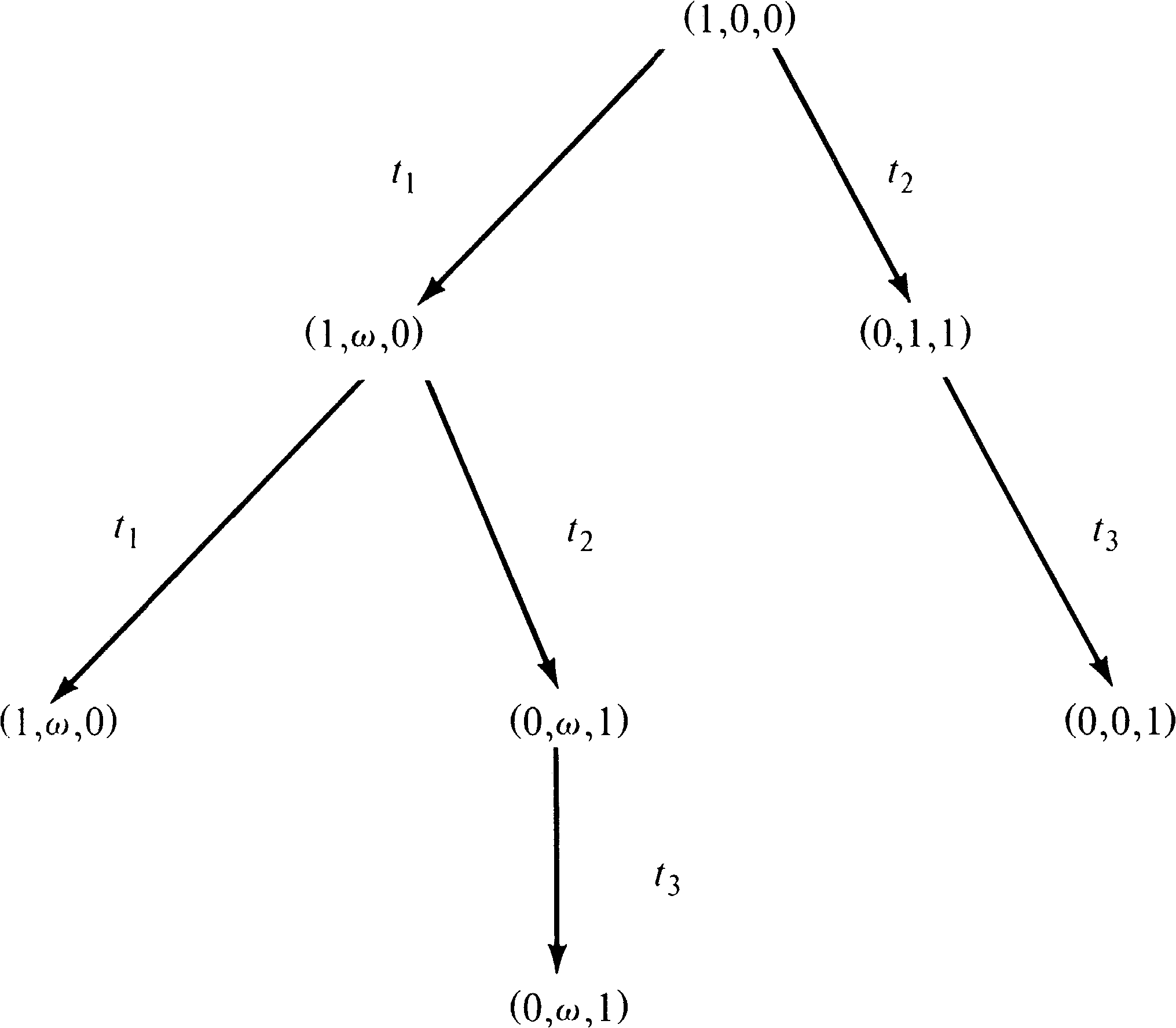
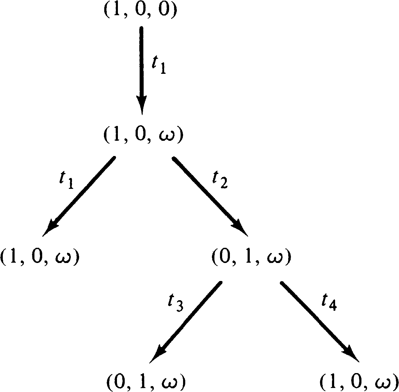
Figure 4.14 is the reachability tree of the Petri net of
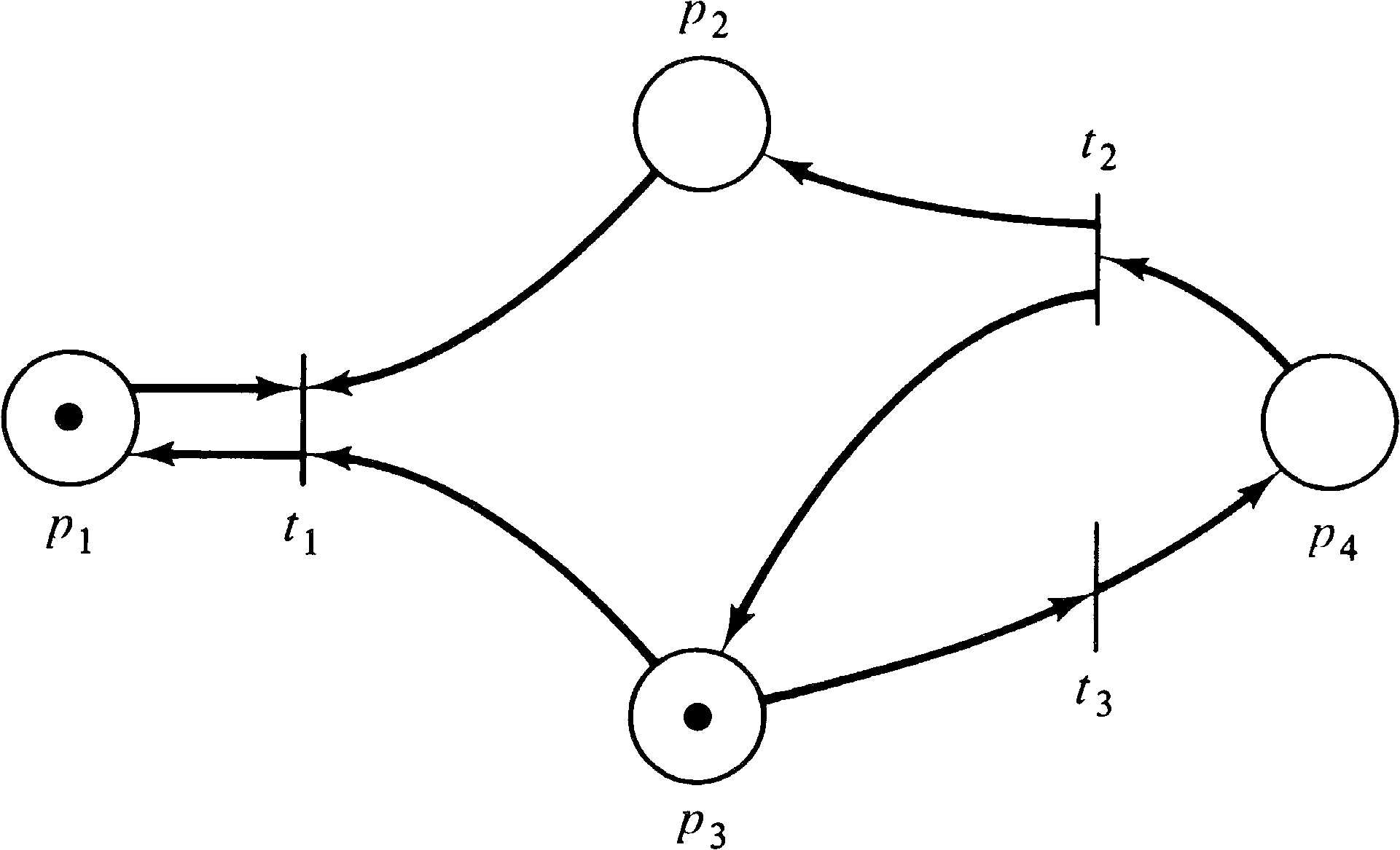
Figure 4.9. Figure 4.15 is the reachability tree of the
Petri net of Figure 4.16.
A very important property of the algorithm to construct a reachability tree is the fact that it terminates. To prove this we must show that the algorithm cannot continue to create new frontier nodes forever. The proof of this property requires three lemmas.
In either case, we have a sequence of vectors that are nondecreasing in their first coordinates. Apply the induction hypothesis on the sequence of n -vectors which result from ignoring the first component of the n + 1 -vectors. The infinite subsequence which is selected in this manner is nondecreasing in each coordinate.
Now we can prove the following theorem.
The reachability tree is an extremely useful tool for the analysis of Petri nets. In the following sections, we show how it can be used to solve several of the problems presented in Section 4.1.
A Petri net is safe if the number of tokens in each place cannot exceed one; a Petri net is bounded if there exists an integer k such that the number of tokens in any place cannot exceed k. Both of these properties can be tested using the reachability tree. A Petri net is bounded if and only if the symbol ω never appears in its reachability tree. The appearance of the symbol ω as part of a reachability tree means that the number of tokens is potentially unbounded; there exists a sequence of transition firings which can be repeated arbitrarily many times to increase the number of tokens to an arbitrary, unbounded number. Thus, if the symbol ω appears, the net is unbounded. In addition, the ω symbol indicates by its position which places are unbounded.
Conversely, if the Petri net is unbounded, then the number of reachable markings is infinite. Since the reachability tree is finite, the symbol ω must occur to represent the infinite number of reachable markings.
If the Petri net is bounded, and the ω symbol is not in the reachability tree, then the Petri net represents a finite state system. The reachability tree then is essentially a state graph and will contain a node corresponding to every reachable marking. This allows any, and all, other analysis questions to be solved by simply the exhaustive examination of the finite set of all reachable markings. For example, to determine the bound on a particular place, generate the reachability tree and scan the tree for the largest value of the component of the markings corresponding to that place. This is the bound on the number of tokens for this place. If the bound for all places is 1, then the net is safe.
Figure 4.17 demonstrates using the reachability tree to
determine boundedness.
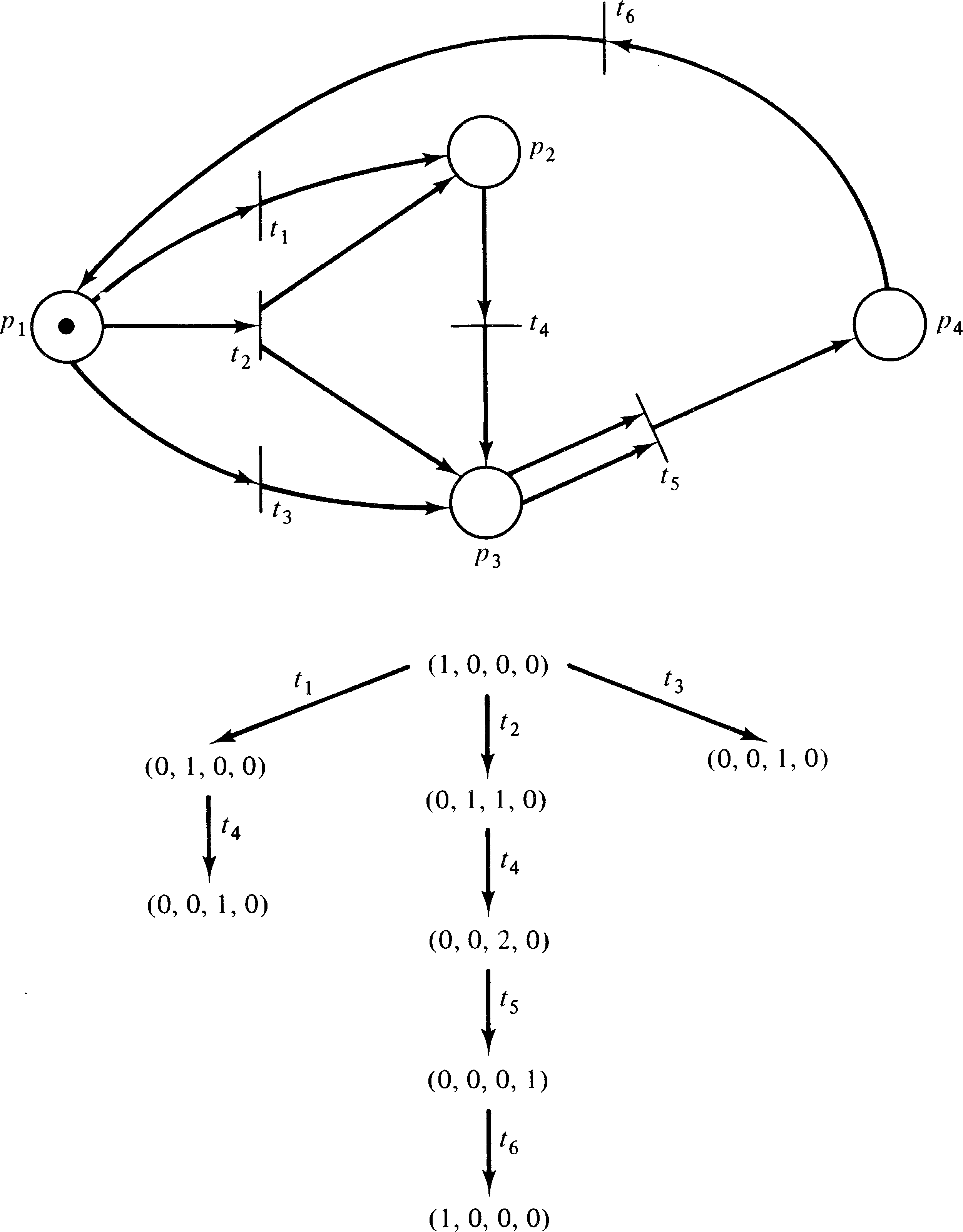
Notice that even for Petri nets which are not bounded (because some place is unbounded) it is possible to determine the bounds for those places which are bounded from the reachability tree. Thus the reachability tree effectively solves the analysis of Petri nets to determine boundedness or safeness for individual places or entire nets.
A Petri net is conservative if it does not lose or gain tokens but merely moves them around. Since two tokens may be encoded as one token which later causes a transition to fire, creating two tokens, a vector of weights defines the value of a token in each place; the weights are nonnegative. A Petri net is conservative with respect to a weighting vector if the weighted sum of tokens is constant over all reachable markings.
Conservation can be effectively tested using the reachability tree. Since the reachability tree is finite, the weighted sum can be computed for each marking. If the sums are the same for each reachable marking, the net is conservative with respect to the given weight. If the sums are not equal, the net is not conservative.
The ω symbol must be carefully considered in the evaluation of conservation. If a marking has ω as the marking for place pi, then the weight of that place must be 0 for the net to be conservative. Remember that the ω symbol represents an infinite set of values. Since all weights are nonnegative, either the weight must be zero (indicating that the value of the number of tokens in this place is unimportant) or positive. If the weight is positive, then the sum will vary for two markings which differ in their ω -component. Hence, if any marking with nonzero weight is ω, the net is not conservative.
The above considerations refer to conservation with respect
to a defined weighting. A Petri net is conservative if it
is conservative with respect to some weight vector w,
with wi > 0 . The reachability tree can be
used to determine if a Petri net is conservative by finding
a positive weight vector w, if one exists. To
determine a positive weight vector with respect to which a
Petri net is conservative, first note that the net must be
bounded. As pointed out above, an unbounded place must have
a weight of zero, which is not possible in a net with
positive weight vector. (If we wish to allow zero
components, we simply set the weights of all unbounded
places to zero and consider further only the remaining
components.) Now if the net is conservative, a weighted
sum, call it s, and a weight vector,
w = ( w1, w2, …, wn ),
exist. For each marking μ [ x ] of the reachability
tree we must have
| w1 ⋅ μ[x]1 + w2 ⋅ μ[x]2 + ⋯ + wn ⋅ μ[x]n | = | s |
| wi > 0, i | = | 1, …, n |
Solution of this system of linear equations is a well-known problem with many algorithms for solution. It can be considered a linear programming problem or simply a system of linear equations. In either case, if a solution exists, it can be computed. (The solutions from these techniques will in general be rational, not integer, but the weights can be multiplied by a common denominator to produce an integer solution.)
If the weights are overly constrained and hence no weighting vector exists, this will be determined. In either case, it can be determined whether or not the Petri net is conservative, and if so, a weight vector is produced.
A final problem which can be solved with the aid of the reachability tree is the coverability problem. For the coverability problem, we wish to determine, for a given marking μ′, if a marking μ′′ ≥ μ′ is reachable. This problem can be solved by inspection of the reachability tree. Given an initial marking μ, we construct the reachability tree. Then we search for any node x, with μ [ x ] ≥ μ′ . If no node is found, the marking μ′ is not covered by any reachable marking; if such a node is found, μ [ x ] gives a reachable marking which covers μ′ .
The path from the root to the covering marking defines the sequence of transitions which leads from the initial marking to the covering marking, and the marking associated with that node defines the covering marking. Again, of course, the symbol ω should be treated as representing an infinite set of values. If a component of the covering marking is ω, then a “loop” will exist in the path from the root to the covering marking. It will be necessary to repeat this loop enough times to raise the corresponding components to not less than the given marking.
Note that if there are several components in the covering
marking which are ω, there may be an interaction
between the marking changes which result from the loops.
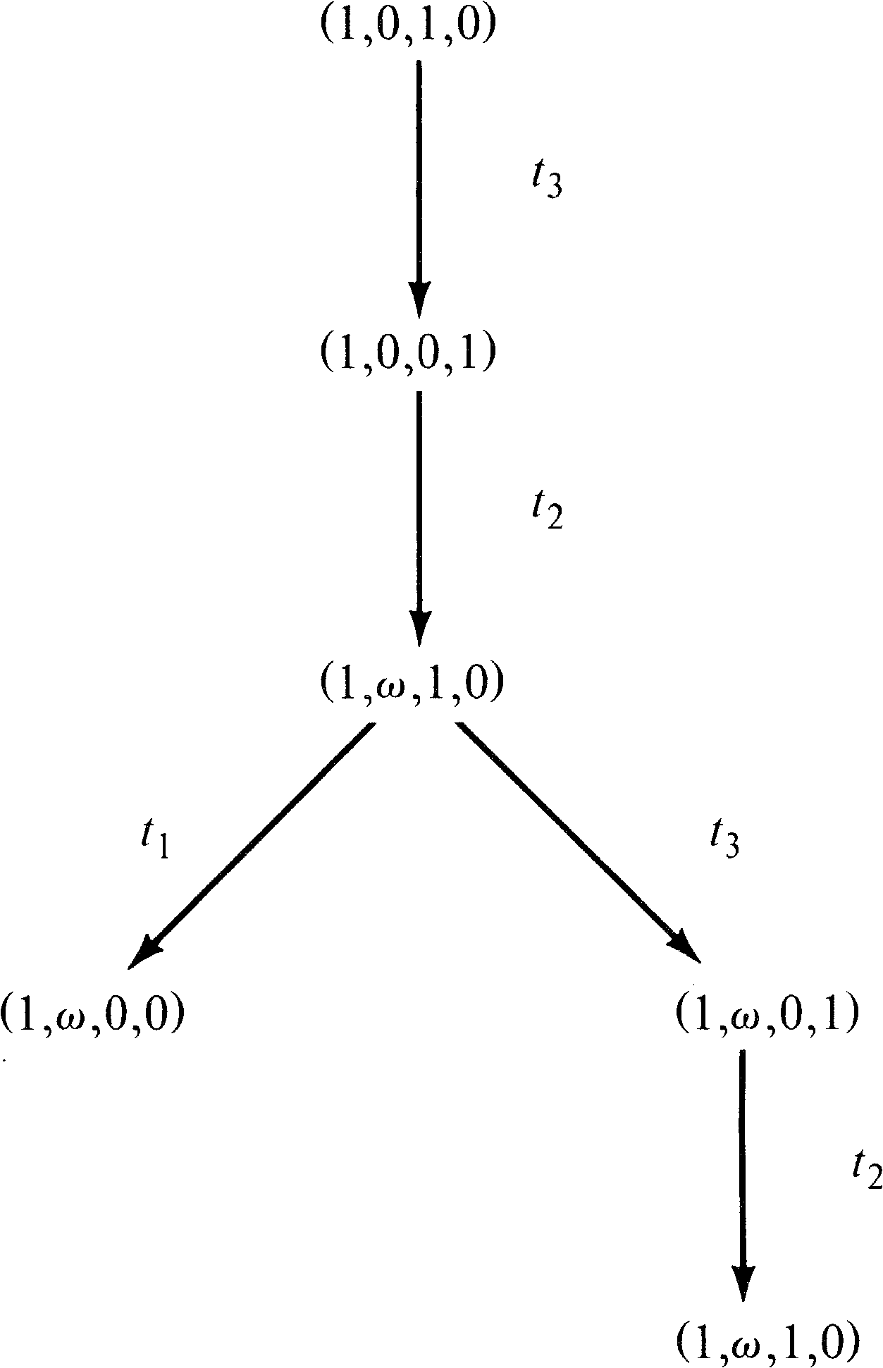
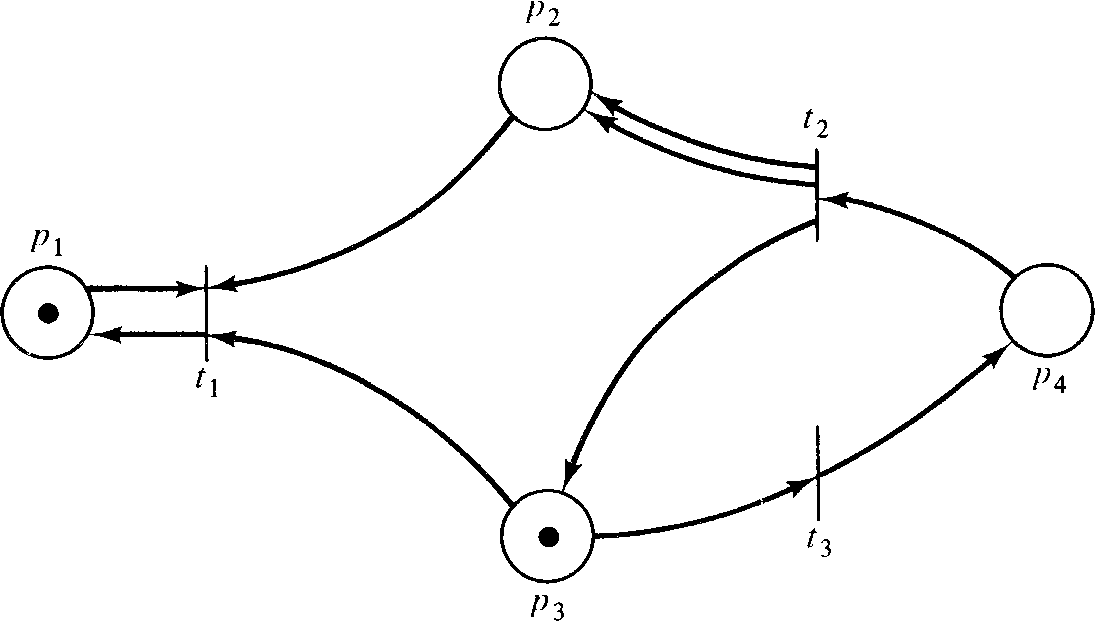
Consider the Petri net of Figure 4.18 and its reachability
tree given in Figure 4.19. According to the analysis given,
the marking (0, 14, 1, 7) is covered in the reachability
set. The path to generate a covering marking consists of
some number of t1 followed by t2
followed by some number of t3. The problem is to
determine how many t1 and t3. Since we
want 14 tokens in p2 and t1 puts a token
in p2, we might try 14 t1. However, we
need 7 t3, and each t3 removes a token
from p2, so we actually need at least 21 t1, then t2, and then at least 7 t3 (but not so many t3 as to empty
p2 too much). Karp and Miller [1968] give an
algorithm which will determine the minimal number of
transition firings needed to cover a given marking.
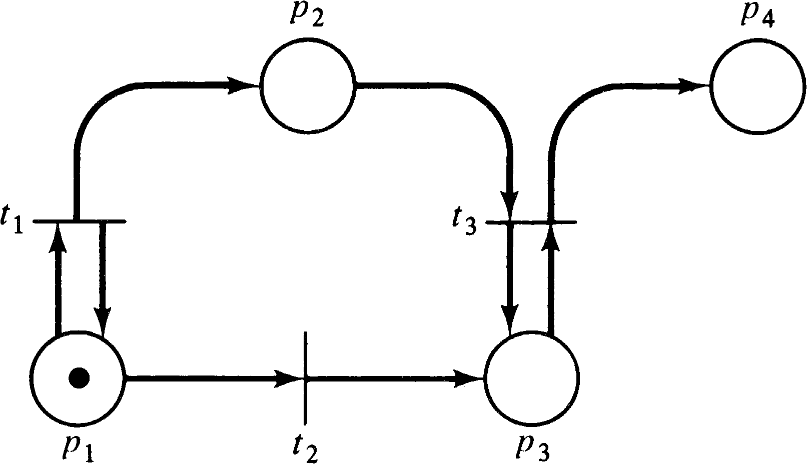
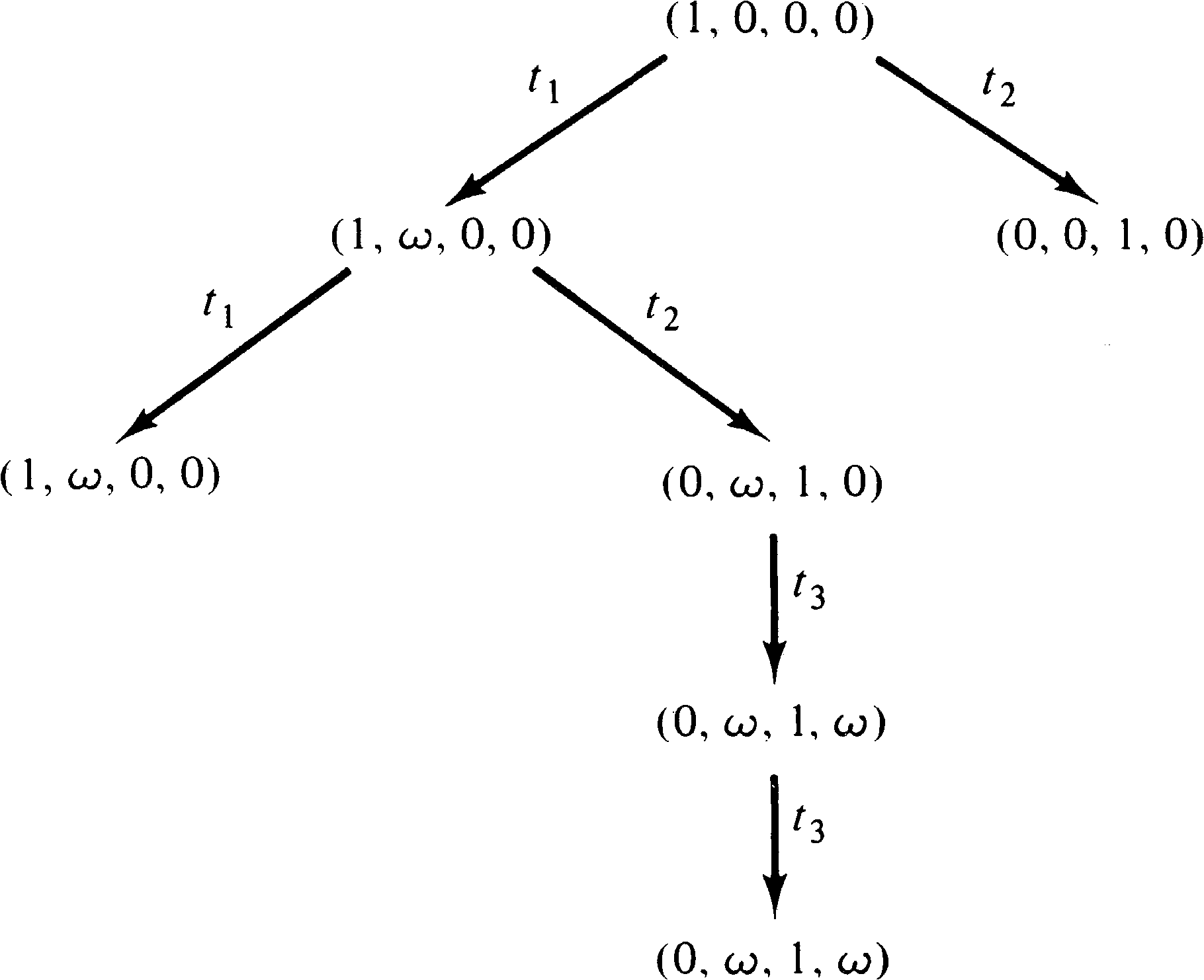
As we have seen, the reachability tree can be used to solve the safeness, boundedness, conservation and coverability problems. Unfortunately, it cannot, in general, be used to solve the reachability or liveness problems or to define or determine which firing sequences are possible. These problems are limited by the existence of the ω symbol. The ω symbol is a loss of information; the individual numbers are discarded, with only the existence of the large number of them being remembered.
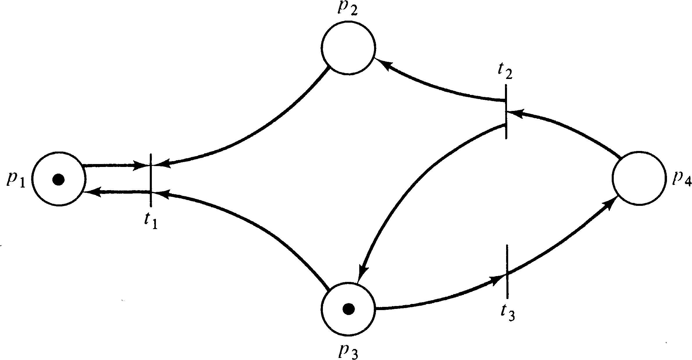
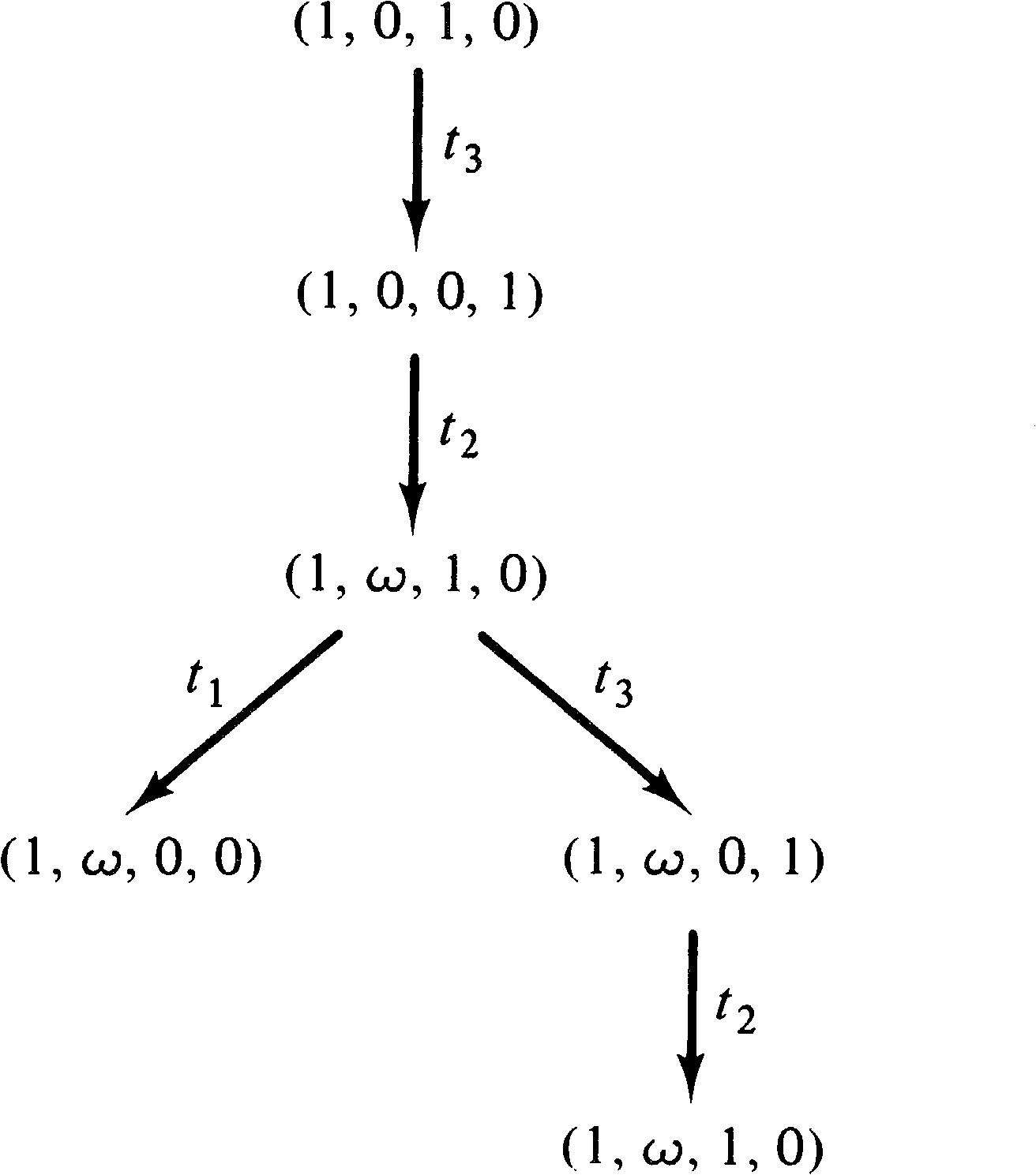
Consider, for example, the Petri nets of Figures 4.20 and 4.21
whose reachability tree is given in Figure 4.22. The same
reachability tree represents these two similar (but
different) Petri nets. The reachability sets are not
the same, however. In the Petri net of Figure 4.20, the
number of tokens in place p2 is always an even
number (until t1 fires), whereas in Figure 4.21 it
may be an arbitrary integer. The ω symbol does not
allow this kind of information to be detected, preventing
the use of the reachability tree to solve the reachability
problem.
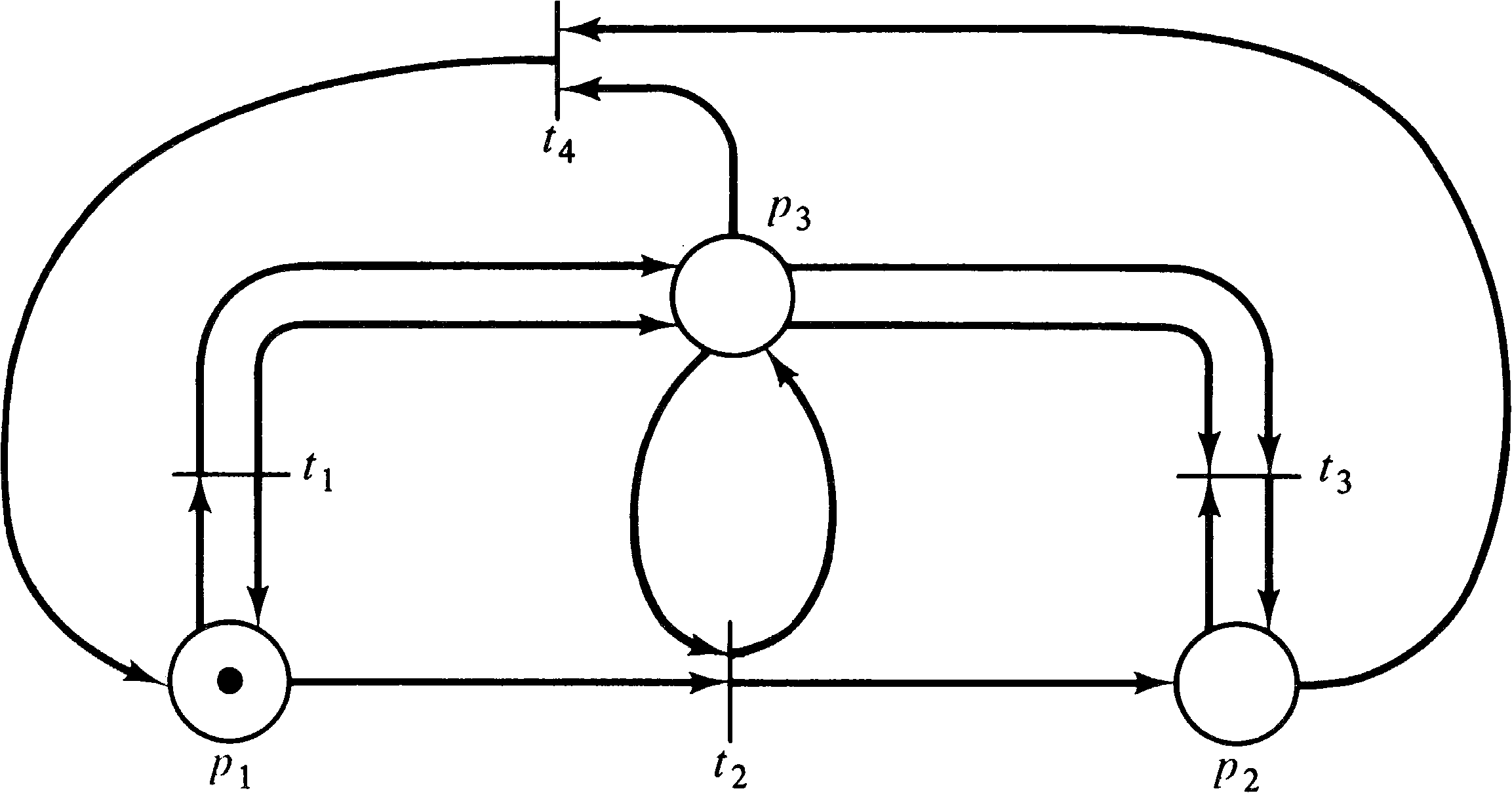
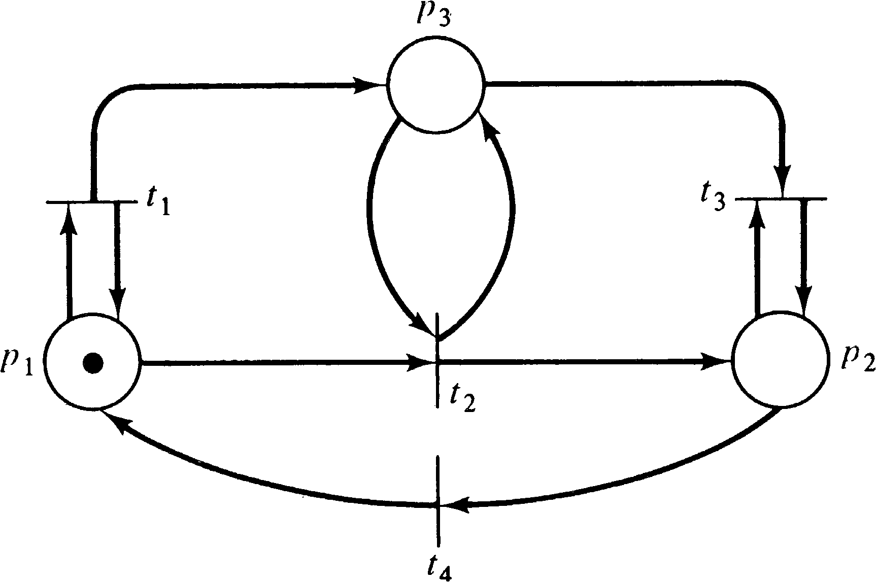
A similar problem exists for the liveness problem. Figures
4.23 and 4.24 are two Petri nets whose reachability tree is
given in Figure 4.25. However, the net in Figure 4.23 can
deadlock (the sequence t1 t2 t3,
for example), while the net in Figure 4.24
cannot. Again, however, the reachability tree cannot
distinguish between these two cases.
Note that although the reachability tree does not necessarily contain enough information to always solve the reachability or liveness problems, it is the case that the tree may have sufficient information to solve many such problems. A net whose reachability tree has a terminal node (one with no successors) is not live (since some reachable marking has no successors). Similarly, a marking μ′ of a reachability problem may appear in the reachability tree, and if so, it is reachable. Also, if a marking is not covered by some node of the reachability tree, then it is not reachable.
These conditions are sufficient to solve some reachability
and liveness problems, but they do not solve these problems
in general. Thus, to solve these two problems, other
approaches are needed.
Exercises
A second approach to the analysis of Petri nets is based on a matrix view of Petri nets. An alternative to the (P, T, I, O) definition of Petri nets is to define two matrices D− and D+ to represent the input and output functions. (These are equivalent to the F and B functions of Hack's Petri net definition; see Section 2.6.) Each matrix is m rows (one for each transition) by n columns (one for each place). We define D− [ j, i ] = # ( pi, I ( tj )) and D+ [ j, i ] = # ( pi, O ( tj )) . D− defines the inputs to the transitions and, D+ defines the outputs.
The matrix definitional form of a Petri net (P, T, D−, D+ ) is equivalent to the standard form we have used but allows the definitions to be recast in vector and matrix terms. Let e [ j ] be the unit m -vector which is zero everywhere except in the j th component. The transition tj is represented by the unit m -vector e [ j ] .
Now a transition tj is enabled in a marking
μ if
| μ ≥ e[j] ⋅ D− |
| δ(μ, tj) | = | μ − e[j] ⋅ D− + e[j] ⋅ D+ |
| = | μ + e[j] ⋅(−D− + D+) | |
| = | μ + e[j] ⋅ D |
Now for a sequence of transition firings
σ = tj1 tj2... tjk, we have
| δ(μ, σ) | = | δ(μ, tj1 tj2... tjk) |
| = | μ + e[j1] ⋅ D + e[j2] ⋅ D + ⋯ + e[jk] ⋅ D | |
| = | μ + (e[j1] + e[j2] + ⋯ + e[jk]) ⋅ D | |
| = | μ + f(σ) ⋅ D |
To show an example of the usefulness of this matrix approach
to Petri nets, consider the conservation problem: Given a
marked Petri net, is it conservative? To show conservation,
it is necessary to find a (nonzero) weighting vector for
which the weighted sum over all reachable markings is
constant. Let w be an n ⨯ 1 column
vector. Then if μ is the initial marking and
μ′ is an arbitrary reachable marking, we need
| μ ⋅ w | = | μ′ ⋅ w |
| μ′ | = | δ(μ, σ) |
| = | μ + f(σ) ⋅ D |
| μ ⋅ w | = | μ′ ⋅ w |
| = | (μ + f(σ) ⋅ D) ⋅ w | |
| = | μ ⋅ w + f(σ) ⋅ D ⋅ w |
| f(σ) ⋅ D ⋅ w | = | 0 |
| D ⋅ w | = | 0 |
The development of this matrix Petri net theory provides a
useful tool for attacking the reachability problem. Assume
that a marking μ′ is reachable from a marking μ .
Then there exists a sequence σ (possibly null) of
transition firings which will lead from μ to μ′ .
This means that f ( σ ) is a solution, in
nonnegative integers, for x in the following matrix
equation.
| μ′ | = | μ + x ⋅ D |
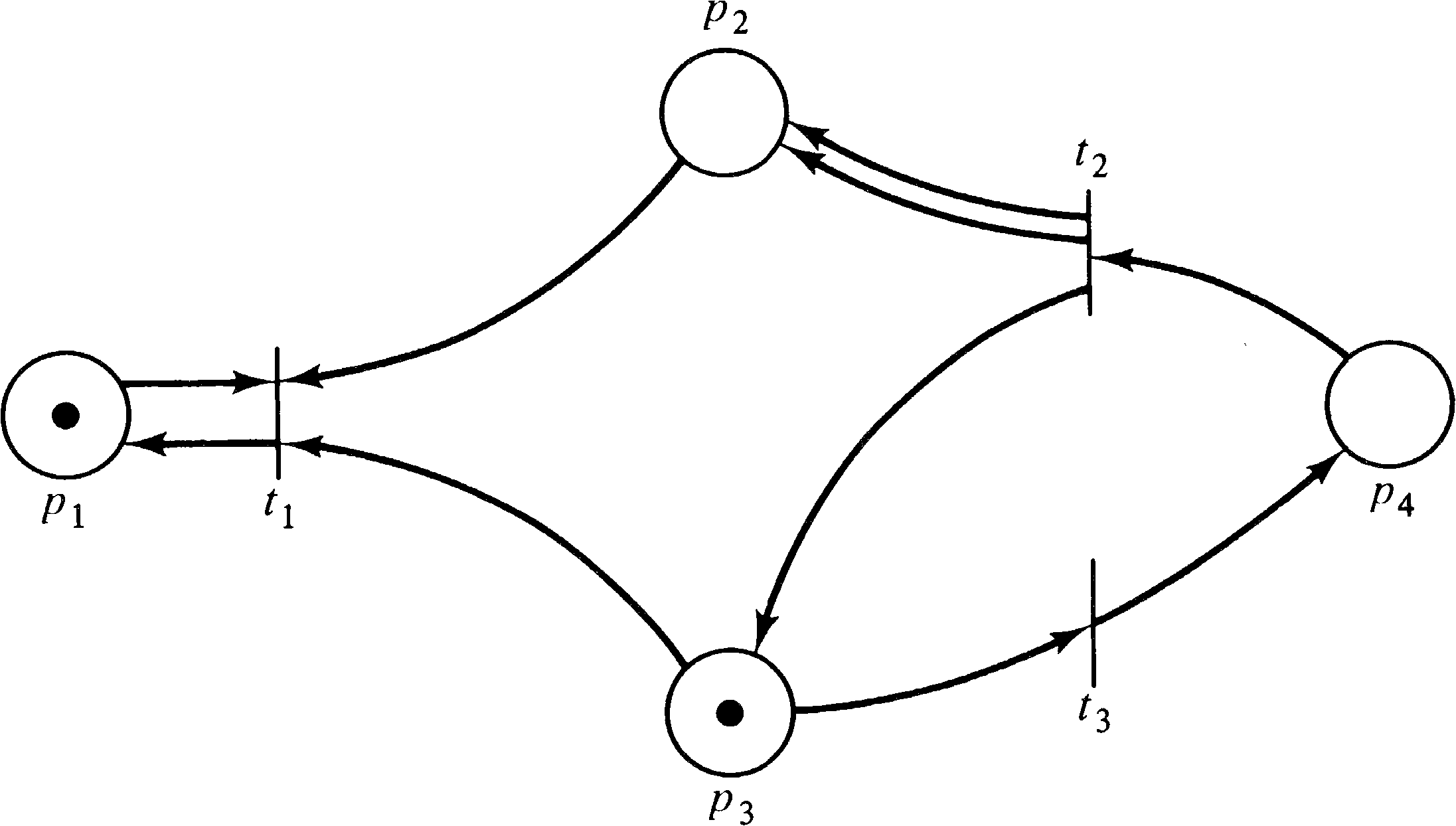
As an example, consider the marked Petri net of Figure 4.26.
The matrices D− and D+ are
| 1 | 1 | 1 | 0 |
| 0 | 0 | 0 | 1 |
| 0 | 0 | 1 | 0 |
| 1 | 0 | 0 | 0 |
| 0 | 2 | 1 | 0 |
| 0 | 0 | 0 | 1 |
| 0 | -1 | -1 | 0 |
| 0 | +2 | +1 | -1 |
| 0 | 0 | -1 | +1 |
| 0 | -1 | -1 | 0 |
| 0 | +2 | +1 | -1 |
| 0 | 0 | -1 | +1 |
| = | (1, 0, 1, 0) + (0, 0, −1, +1) | |
| = | (1, 0, 0, 1) |
| 0 | -1 | -1 | 0 |
| 0 | +2 | +1 | -1 |
| 0 | 0 | -1 | +1 |
| = | (1, 0, 1, 0) + (0, 3, −1, 0) | |
| = | (1, 3, 0, 0) |
To determine if the marking (1, 8, 0, 1) is reachable from
the marking (1, 0, 1, 0), we have the equation
| 0 | -1 | -1 | 0 |
| 0 | +2 | +1 | -1 |
| 0 | 0 | -1 | +1 |
| 0 | -1 | -1 | 0 |
| 0 | +2 | +1 | -1 |
| 0 | 0 | -1 | +1 |
We can further show that marking (1, 7, 0, 1) is not
reachable from the marking (1, 0, 1, 0), since the matrix
equation
| 0 | -1 | -1 | 0 |
| 0 | +2 | +1 | -1 |
| 0 | 0 | -1 | +1 |
| 0 | -1 | -1 | 0 |
| 0 | +2 | +1 | -1 |
| 0 | 0 | -1 | +1 |
The matrix approach to the analysis of Petri nets has great
promise but also has some severe problems. First notice
that the matrix D by itself does not properly reflect the
structure of the Petri net. Transitions which have both
inputs and outputs from the same place (self-loops) will be
represented in the same position of the D− and D+
matrices and so will cancel out in the D = D+ − D−
matrix. This was reflected in the previous example by place
p1 and transition t1.
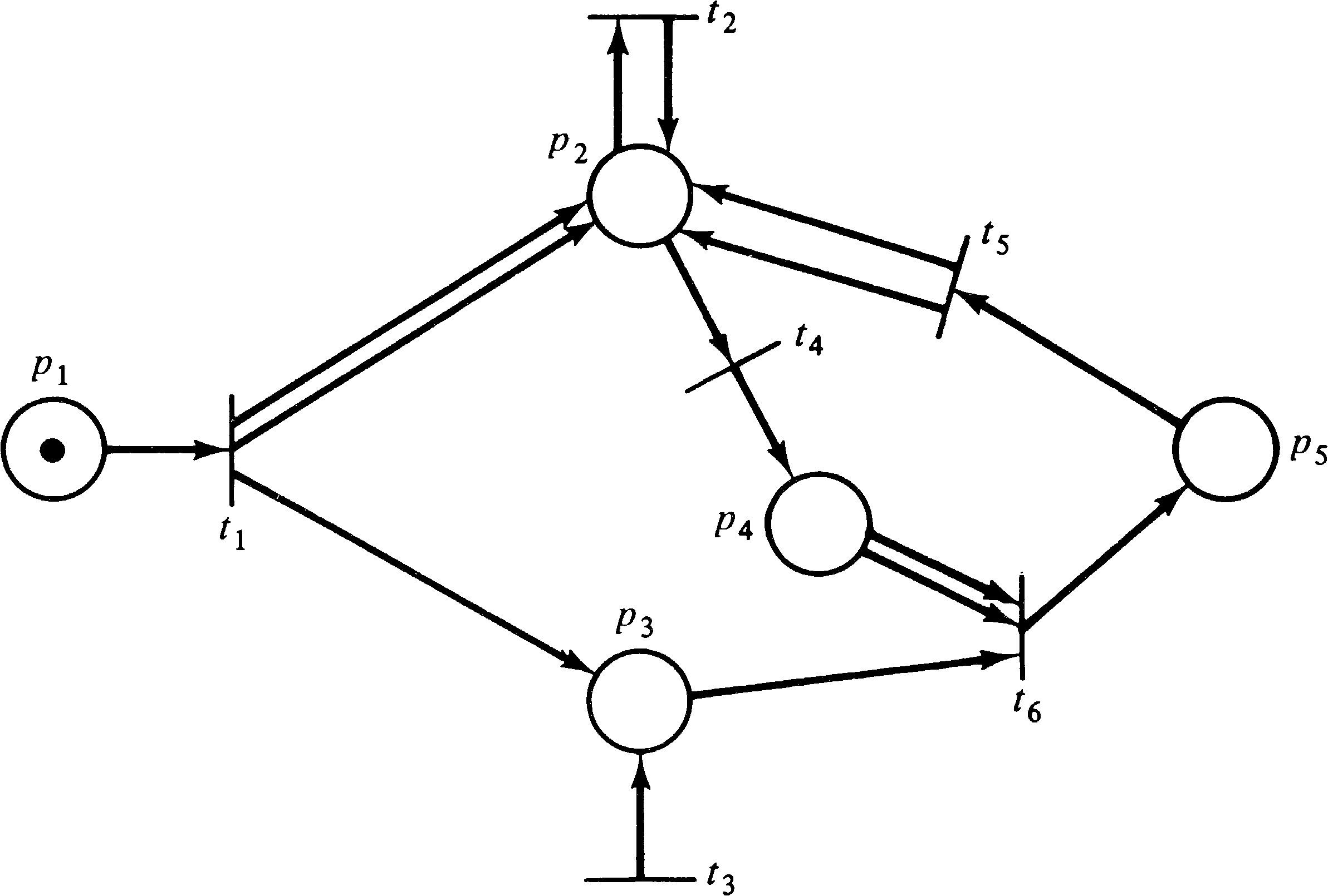
Another problem is the lack of sequencing information in the
firing vector. Consider the Petri net of Figure 4.27.
Assume we wish to determine if the marking (0, 0, 0, 0, 1)
is reachable from (1, 0, 0, 0, 0). Then one equation is
| -1 | 2 | 1 | 0 | 0 |
| 0 | 0 | 0 | 0 | 0 |
| 0 | 0 | 1 | 0 | 0 |
| 0 | -1 | 0 | 1 | 0 |
| 0 | 2 | 0 | 0 | -1 |
| 0 | 0 | -1 | -1 | 1 |
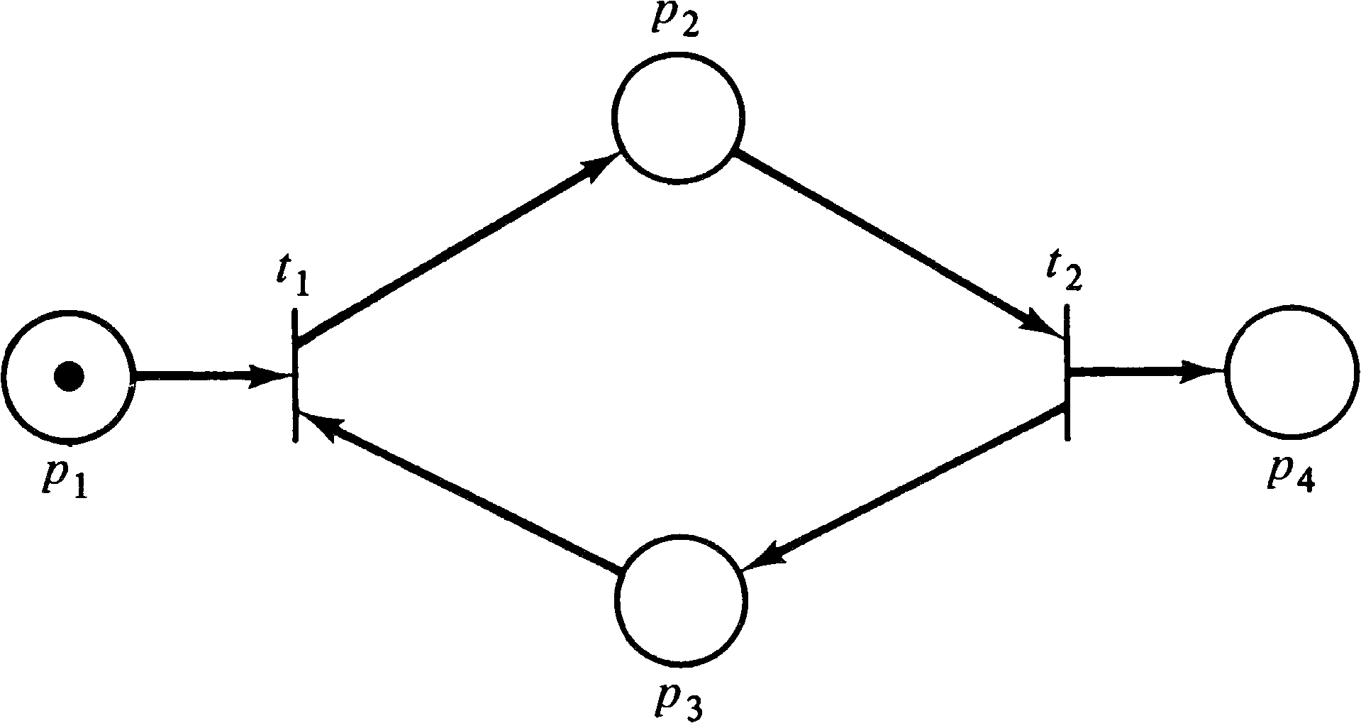
Another problem is that although a solution to Equation
(4.1) is necessary for reachability, it is not
sufficient. Consider the simple Petri net of Figure
4.28. If we wish to determine if (0, 0, 0, 1) is reachable
from (1, 0, 0, 0) we must solve the equation
| -1 | +1 | -1 | 0 |
| 0 | -1 | +1 | +1 |
The possibility of spurious solutions to Equation (4.1) --
solutions which do not correspond to possible transition
sequences -- has resulted in only limited research on the
matrix representation of Petri nets. The best research on
this approach has been by Murata [1975; 1977a; 1977b].
4.3. Further Reading
Holt et al. [1968] and Holt and Commoner [1970] defined some of the early analysis problems for Petri nets -- liveness and safeness -- and these have continued as major problems for analysis. Liveness has been studied by Commoner [1972], Lautenbach [1975], and Lien [1976a]. Keller [1972] also considered liveness plus other problems. Lien [1976a] defined the conservation problem.
Karp and Miller [1968] first described the reachability tree construction and proved that it was finite. The coverability and reachability problems were defined by them, as were the equivalence and containment problems. These later problems were the subject of [Baker 1973b], while [Nash 1973] is a brief statement of the reachability problem. Hack [1974a] brings most of these problems together in one place and shows how the reachability tree can be used for some of them.
The matrix approach was considered by Peterson [1973] but
was found to be of limited usefulness. Murata, with a better
background in linear algebra, has done quite a bit more with
this approach in [Murata and Church 1975; Murata 1975;
Murata et al. 1975; Murata 1977a; Murata 1977b].
4.4. Topics for Further Study
With this motivation, let Σf be the sum over all components of a firing vector f. That is, if f = ( f1, f2, …, fm ), then Σf = f1 + f2 + ⋯ + fm. Now consider that if a sequence σ exists which will take a Petri net from a marking μ to a marking μ′, then Equation (4.1) has a solution which is the firing vector f ( σ ) for σ . The sequence σ can be determined from the firing vector f ( σ ) by simply enumerating all possible sequences of length equal to Σ f ( σ ) and trying each to determine if it (1) is legal and (2) leads from μ to μ′ . For a Petri net with m transitions, there are at most m Σf possible sequences of length Σf. This can, in fact, be reduced further. Since we know how many times transition t1 fires ( f1 ), how many times t2 fires ( f2 ), and so on, we need examine no more than the Σf ! possible orderings of f1 firings of t1, f2 firings of t2, and so on.
This would seem to provide a decision procedure for determining if μ′ is reachable from μ . First solve the matrix equation μ′ = μ + f ⋅ D. If there is no solution, μ′ is not reachable from μ . If a solution f exists, then examine all Σf ! possible orderings of the transitions. If any of these transition sequences is legal, then μ′ is reachable from μ, and we have the sequence of transitions which takes us from μ to μ′ .
There is only one hitch. The solution f may not be unique but may be a (infinite) set of firing vectors represented by a set of expressions (as illustrated above for the analysis of Figure 4.27). Research is needed to determine if it can be shown that it is possible to determine reachability in this case. In the easiest case, it may be that either all solutions represented by an expression firing vector correspond to legal solutions, or none of the solutions do. In this case, we merely pick any solution and follow the above procedure of checking all possible orderings. More likely, however, some solutions may work while others fail. Since we cannot try all solutions (possibly infinite number), research must be done to determine which solutions should be tried.
| Home | Comments? |